5-1 PREPARATION
‘‘
REQUIRED TEST EQUIPMENT
‘‘
ADJUSTMENT FREQUENCY DATA
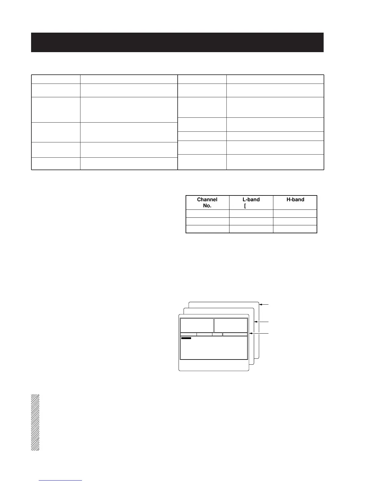
Before starting the adjustment, back up the original frequen-
cy data and program adjustment frequency data at right
using the optional programming software (EX-2057 Rev. 1.0
or later for IC-F310/F320, CS-F300S for IC-F310S/F320S),
cloning cable (OPC-478), and adaptor cable (OPC-592) for
your convenience.
‘‘
TRIMMER ADJUSTMENT
When you adjust the contents on page 5-4, TRIMMER ADJUSTMENT, the optional EX-2057, OPC-478 and JIG CABLE are
required.
• STARTING TRIMMER ADJUSTMENT
Turn the transceiver power ON, connect a computer to the [MIC] jack using the optional OPC-478 CLONING CABLE and JIG
CABLE, then start up the "ADJUST" program in EX-2057 or CS-F300S.
•
STARTING THE PROGRAM
q Boot up DOS.
w Insert the EX-2057 or CS-F300S backup disk into drive A.
e Type the following to start up the program:
ADJ>ADJUST [/A : /B]*
1
[/1 : /2]*
2
[Enter]
• The adjustment screen appears after reading set data
from the transceiver.
r After the adjustment screen appears, set or modify the
data as desired.
*
1
PLL reference crystal type.
/A: Normal crystal type. (You must select [/A] for IC-
F310/F310S/F320/F320S’s adjustment.)
/B: This does not activate for IC-F310/F320’s adjust-
ment.
*
2
RS-232C port number.
NOTE: When the EEPROM (FRONT unit; IC3) is replaced or the transceiver displays an error message and beeps, the
following operation is necessary before starting the ADJUSTMENT.
1. Download the programmed data using the EX-2057 or CS-F300S from an exact same version of the transceiver, then
save it. (See the instructions for detailed operation.)
2. Set the cursor to the [MODEL] and push the [
↓] key on the computer keyboard.
3. Type "RESERVE" then push [Enter].
"Reserved" indicator flashes at the right hand, top corner on the computer screen.
4. Connect the transceiver which has been repaired, then write the data to the transceiver.
EQUIPMENT
DC power supply
RF power meter
(terminated type)
Frequency counter
FM deviation meter
DC voltmeter
GRADE AND RANGE
Output voltage : 13.2 (13.6) V DC
Current capacity : 15 A or more
Measuring range : 1–75 W
Frequency range : 100–300 MHz
Impedance : 50 Ω
SWR : Less than 1.2 : 1
Frequency range : 0.1–300 MHz
Frequency accuracy : ±1 ppm or better
Sensitivity : 100 mV or better
Frequency range : DC–300 MHz
Measuring range : 0 to ±10 kHz
Input impedance : 50 kΩ/V DC or better
EQUIPMENT
Audio generator
Standard signal
generator (SSG)
Oscilloscope
AC millivoltmeter
External speaker
Attenuator
GRADE AND RANGE
Frequency range : 300–3000 Hz
Measuring range : 1–500 mV
Frequency range : 0.1–300 MHz
Output level : 0.1 µV–32 mV
(–127 to –17 dBm)
Frequency range : DC–20 MHz
Measuring range : 0.01–20 V
Measuring range : 10 mV–10 V
Input impedance : 4 Ω
Capacity : 5 W or more
Power attenuation : 50 or 60 dB
Capacity : 100 W or more
• ADJUSTMENT FREQUENCY
SECTION 5 ADJUSTMENT PROCEDURES
5 - 1
A:\>CD ADJ
Boot up DOS, and
change the directory.
Startup command.
Program starts up,
then the adjustment
screen appears after
reading set data from
the transceiver.
A:\>ADJ>ADJUST [/A] [/1]
Memory CH
: 1
Power(Hi) : 142
‘ ‘ ‘ ‘ ‘ ‘ ‘ ‘ ‘ ‘ ‘ – – – – – – – – –
Power(L2) : 88
‘ ‘ ‘ ‘ ‘ ‘ ‘ – – – – – – – – – – – – – –
Power(L1) : 44
‘ ‘ ‘ – – – – – – – – – – – – – – – – – – –
M O D N : 68
‘ ‘ ‘ ‘ ‘– – – – – – – – – – – – – – – – –
M O D W : 137
‘ ‘ ‘ ‘ ‘ ‘ ‘ ‘ ‘ ‘ ‘ – – – – – – – – –
DTCS N : 24
‘ ‘ – – – – – – – – – – – – – – – – – – – –
DTCS W : 51
‘ ‘ ‘ ‘– – – – – – – – – – – – – – – – – –
TXF SET :
BPF T1 : -70
‘ ‘ ‘ ‘ ‘ – – – – – – – – – – – – – – – – –
BPF T2 : -72
‘ ‘ ‘ ‘ – – – – – – – – – – – – – – – – – –
BPF T3 : -76
‘ ‘ ‘ ‘ – – – – – – – – – – – – – – – – – –
BPF T4 : -70
‘ ‘ ‘ ‘ ‘– – – – – – – – – – – – – – – – –
AF Vol.L : 1
– – – – – – – – – – – – – – – – – – – – – – –
S Q L : 10
‘ ‘ – – – – – – – – – – – – – – – – – – – –
∗∗∗∗∗ Trimmer Control Software for IC–F300 Series ∗∗∗∗∗ Rev. 1.0
A/D VIN 177 : B1h 13.88V
A/D TEMPS 180: B4h 27.70'C
A/D LVIN 160 : A0h 3.38V
A/D SD 25 : 19h 0.49V
D/A DTCS BL 36 : 24h 14.12%
D/A SQL Lev 10 : 0Ah 3.92%
D/A BP T1 170: AAh 2.93V
D/A BP T2 188: BCh 3.16V
D/A BP T3 184: B8h 3.11V
D/A T4/POW 190 : BEh 3.18V
D/A REF 87 : 57h 1.72V
D/A AF/Dev 1: 01h 0.39%
RX:155.00000MHz TX:155.00000MHz
MODE: Wide
POW: High
[Space]: A/D, D/A Read
[TAB]: Display Parameters [F8] at BPF: Sweep [F9] at BPF T1: Sweep T1
~
T4
[Enter] at TXF: REF Set Mode ↑ / ↓: Cursor Up/Down < / > : –/+ ESC : Quit
 Loading...