Memory CH
: 1
Power(Hi) : 142
‘ ‘ ‘ ‘ ‘ ‘ ‘ ‘ ‘ ‘ ‘ – – – – – – – – –
Power(L2) : 88
‘ ‘ ‘ ‘ ‘ ‘ ‘ – – – – – – – – – – – – – –
Power(L1) : 44
‘ ‘ ‘ – – – – – – – – – – – – – – – – – – –
M O D N : 68
‘ ‘ ‘ ‘ ‘– – – – – – – – – – – – – – – – –
M O D W : 137
‘ ‘ ‘ ‘ ‘ ‘ ‘ ‘ ‘ ‘ ‘ – – – – – – – – –
DTCS N : 24
‘ ‘ – – – – – – – – – – – – – – – – – – – –
DTCS W : 51
‘ ‘ ‘ ‘– – – – – – – – – – – – – – – – – –
TXF SET :
BPF T1 : -70
‘ ‘ ‘ ‘ ‘ – – – – – – – – – – – – – – – – –
BPF T2 : -72
‘ ‘ ‘ ‘ – – – – – – – – – – – – – – – – – –
BPF T3 : -76
‘ ‘ ‘ ‘ – – – – – – – – – – – – – – – – – –
BPF T4 : -70
‘ ‘ ‘ ‘ ‘– – – – – – – – – – – – – – – – –
AF Vol.L : 1
– – – – – – – – – – – – – – – – – – – – – – –
S Q L : 10
‘ ‘ – – – – – – – – – – – – – – – – – – – –
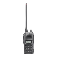
∗∗∗∗∗ Trimmer Control Software for IC–F300 Series ∗∗∗∗∗ Rev. 1.0
A/D VIN 177 : B1h 13.88V
A/D TEMPS 180: B4h 27.70'C
A/D LVIN 160 : A0h 3.38V
A/D SD 25 : 19h 0.49V
D/A DTCS BL 36 : 24h 14.12%
D/A SQL Lev 10 : 0Ah 3.92%
D/A BP T1 170: AAh 2.93V
D/A BP T2 188: BCh 3.16V
D/A BP T3 184: B8h 3.11V
D/A T4/POW 190 : BEh 3.18V
D/A REF 87 : 57h 1.72V
D/A AF/Dev 1: 01h 0.39%
RX:155.00000MHz TX:155.00000MHz
MODE: Wide
POW: High
[Space]: A/D, D/A Read
[TAB]: Display Parameters [F8] at BPF: Sweep [F9] at BPF T1: Sweep T1
~
T4
[Enter] at TXF: REF Set Mode ↑ / ↓: Cursor Up/Down < / > : –/+ ESC : Quit
PLL lock voltage
Internal temperature
Operating channel
RF output power
FM deviation
Receive sensitivity
Reference frequency
Connected DC voltage
SQL level
DTCS balance level
Volume
Squelch
DTCS balance
The above values for settings are examples only. Each transceiver has its
own specific values for each setting.
NOTE:
 Loading...