35
6
OPTIONAL UNIT INSTALLATION
■ UT-109 and UT-110 installation
The following PC board modification is required when install-
ing the optional UT-109 or UT-110:
q Rotate [VOL] to turn the power OFF, and remove the bat-
tery pack. (p. 2)
w Remove the unit cover as shown on p. 34 (Optional unit
installation).
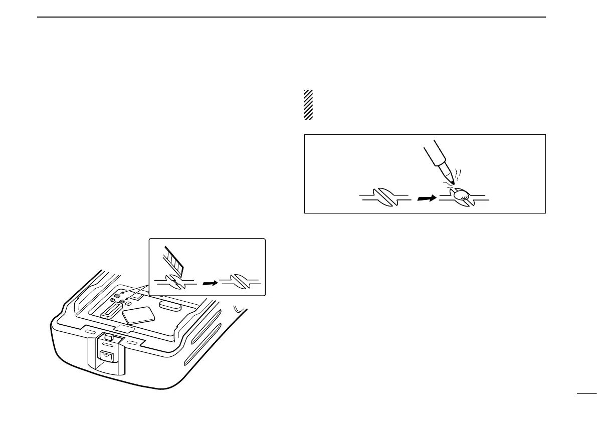
e Cut the pattern on the PCB at the TX mic circuit (C) and
RX AF circuit (F) as shown below.
r Install the scrambler unit as described in the Optional unit
installation (p. 34).
t Replace the unit cover and the battery pack, then rotate
[VOL] to turn the power ON.
NOTE: When uninstalling the scrambler unit
Be sure to re-solder the disconnected points at left, other
-
wise no TX modulation or AF output is available.
 Loading...