5 - 5
5-3 TRANSMIT ADJUSTMENT
Select an adjustment item using [
↑
] / [
↓
] keys, then set to the specifi ed value using [
←
] / [
→
] keys on the connected PC’s keyboard.
ADJUSTMENT ADJUSTMENT CONDITION
MEASUREMENT
VALUE
UNIT OPERATION
TRANSMIT
OUTPUT
POWER
[Power (Hi)]
1 • Channel
• Transmitting
: 1-1 PA-C
UNIT
Connect an RF power meter to
the RF connector (PA-C UNIT;
J701).
0.50 W
FM
DEVIATION
[MOD]
1
• Channel : 1-1
PA-C
UNIT
Connect the FM deviation meter
to RF connector (PA-C UNIT;
J701) through an attenuator.
±2.05 to ±2.15 kHz
• Connect an audio generator to the JIG
cable and set as;
Frequency : 1.0 kHz
Level : 150 mV rms
• Transmitting
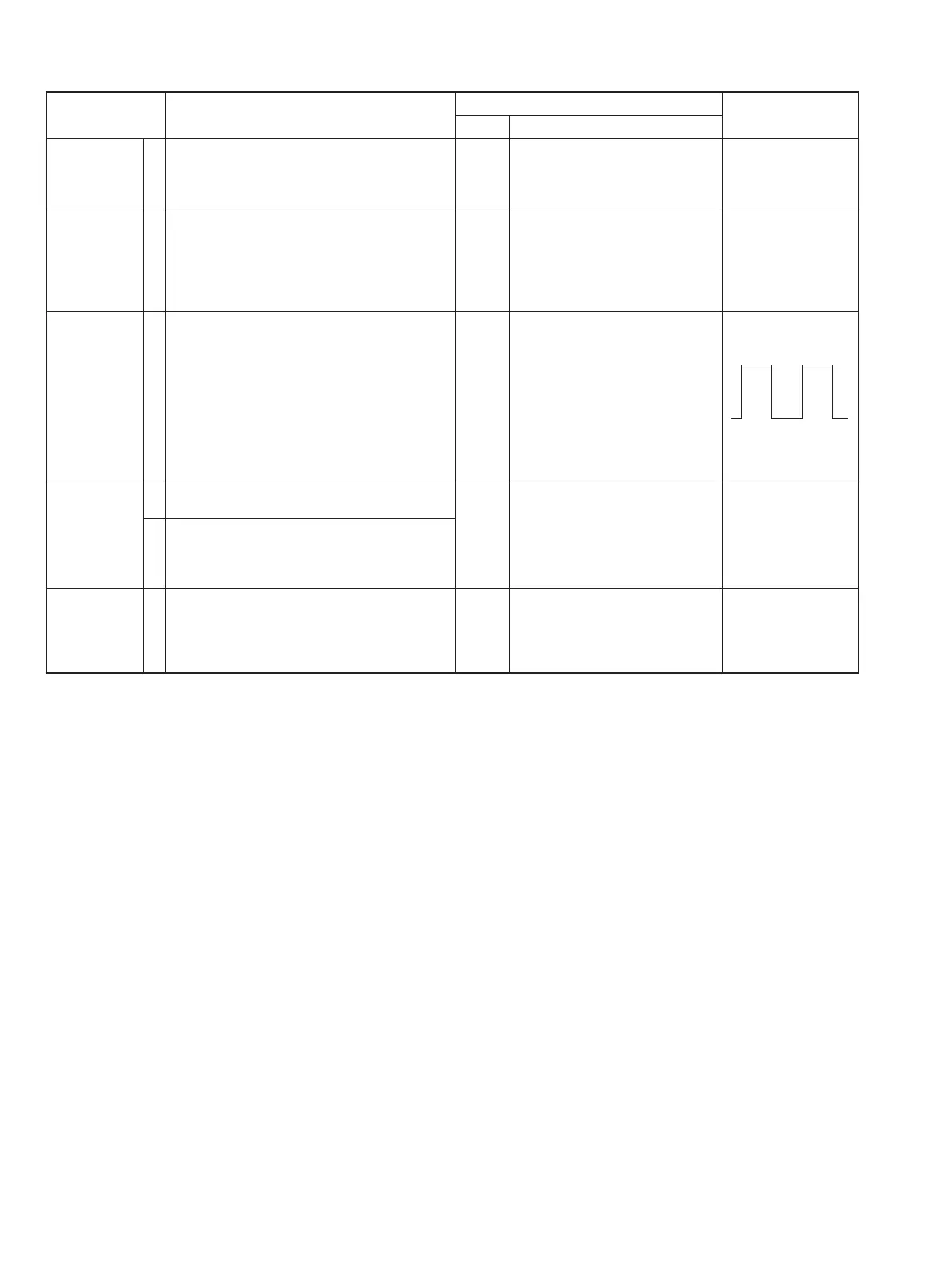
MODULATION
BALANCE
[BAL]
1 • Channel : 1-2 PA-C
UNIT
Connect the FM deviation meter
to the RF connector (PA-C UNIT;
J701) through an attenuator.
Set to square wave form
• No audio applied to the JIG cable.
• Set an FM deviation meter same as;
HPF
LPF
De-emphasis
Detector
: OFF
: 20 kHz
: OFF
: (P–P)/2
• Set the FM deviation meter to same condi-
tion as “FM DEVIATION."
• Transmitting
DIGITAL
DEVIATION
[Dig MOD]
1
• Mode preset
[Digital Mode] : 7
PA-C
UNIT
Connect an FM deviation meter to
RF connector (PA-C UNIT; J701)
through an attenuator.
±1.39 to ±1.43 kHz
2
• Channel : 1-4
• Set the FM deviation meter to same condi-
tion as “FM DEVIATION."
• Transmitting
CTCSS/DTCS
DEVIATION
[CTCSS/DTCS]
1
• Channel : 1-3
PA-C
UNIT
Connect an FM deviation meter to
RF connector (PA-C UNIT; J701)
through an attenuator.
±0.33 to
±
0.37 kHz
• No audio applied to the JIG cable.
• Set the FM deviation meter to same condi-
tion as FM DEVIATION."
• Transmitting
 Loading...