e
r
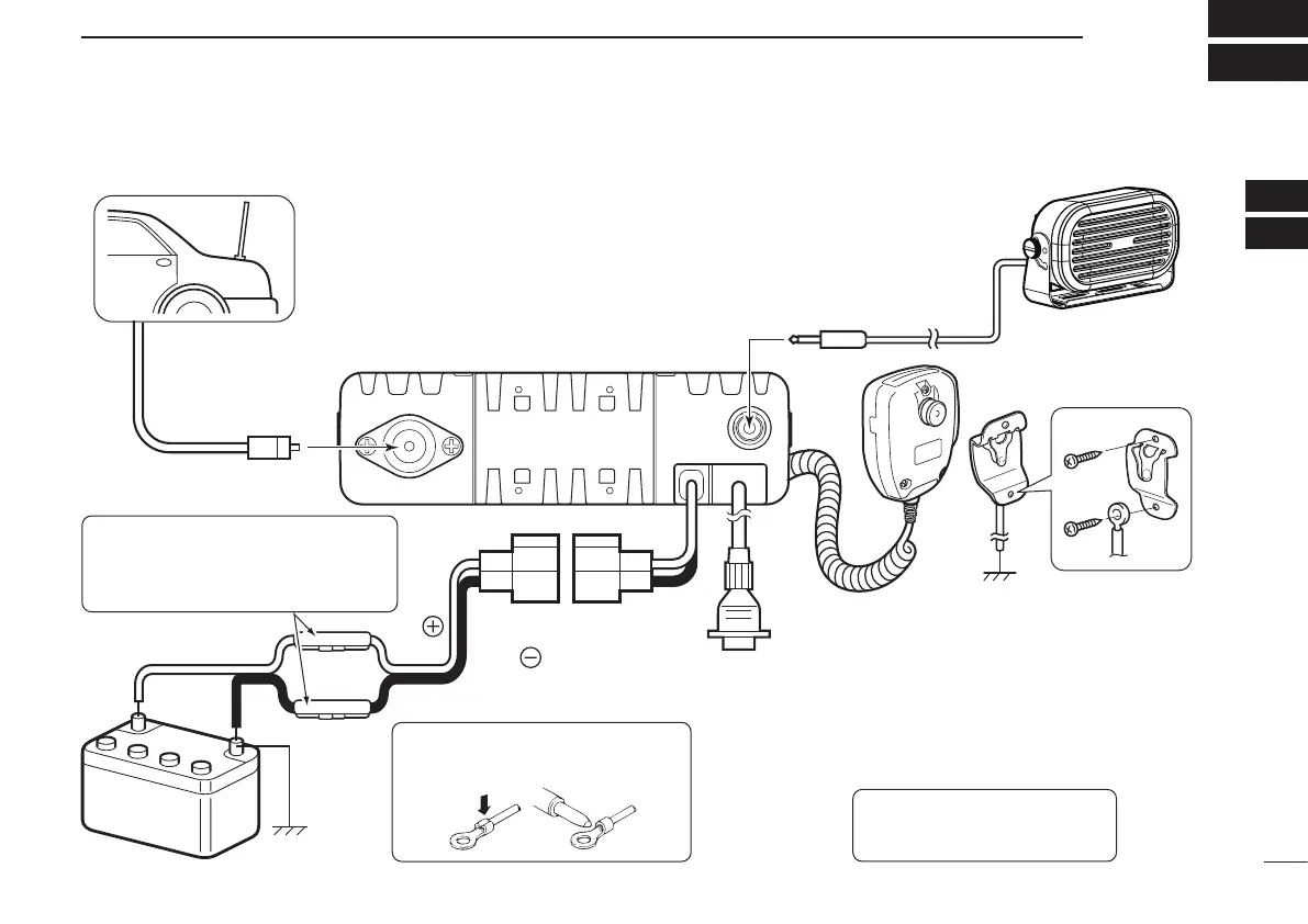
Antenna
Black
Red
12V
Battery
Solder
Crimp
NOTE: Use the terminals as shown
for the cable connections.
q ANTENNA CONNECTOR
Connect to an antenna. Ask your
dealer about antenna selection
and placement.
q
w
w EXTERNAL SPEAKER JACK
Connect to a 4 to 8 ø external speaker.
e MICROPHONE HANGER
Connect the supplied micro-
phone hanger to the vehicle’s
ground for microphone ON/OFF
hook functions. (See page 1)
r
OPTIONAL CABLE (OPC-1939, OPC-2078
)
t
t DC POWER RECEPTACLE
Connect to a 12 V DC battery.
Pay attention to polarities.
Optional speaker
Connect an external modem, dimmer
control, etc.
NOTE: No Digital Modulation “IN” using
accessory cables.
R WARNING! NEVER connect
to a 24 V battery. This could
damage the transceiver.
R WARNING! NEVER remove the
fuse-holders from the DC power cable.
(Depending on version, the fuse holder
may not be attached to the black cable.)
 Loading...