17
3
CONNECTION AND MAINTENANCE
1
2
3
4
5
6
7
8
9
10
11
12
13
14
15
16
■ Antenna
A key element in the performance of any communication sys-
tems is its antenna. Contact your dealer for more information
regarding antennas and how to install them.
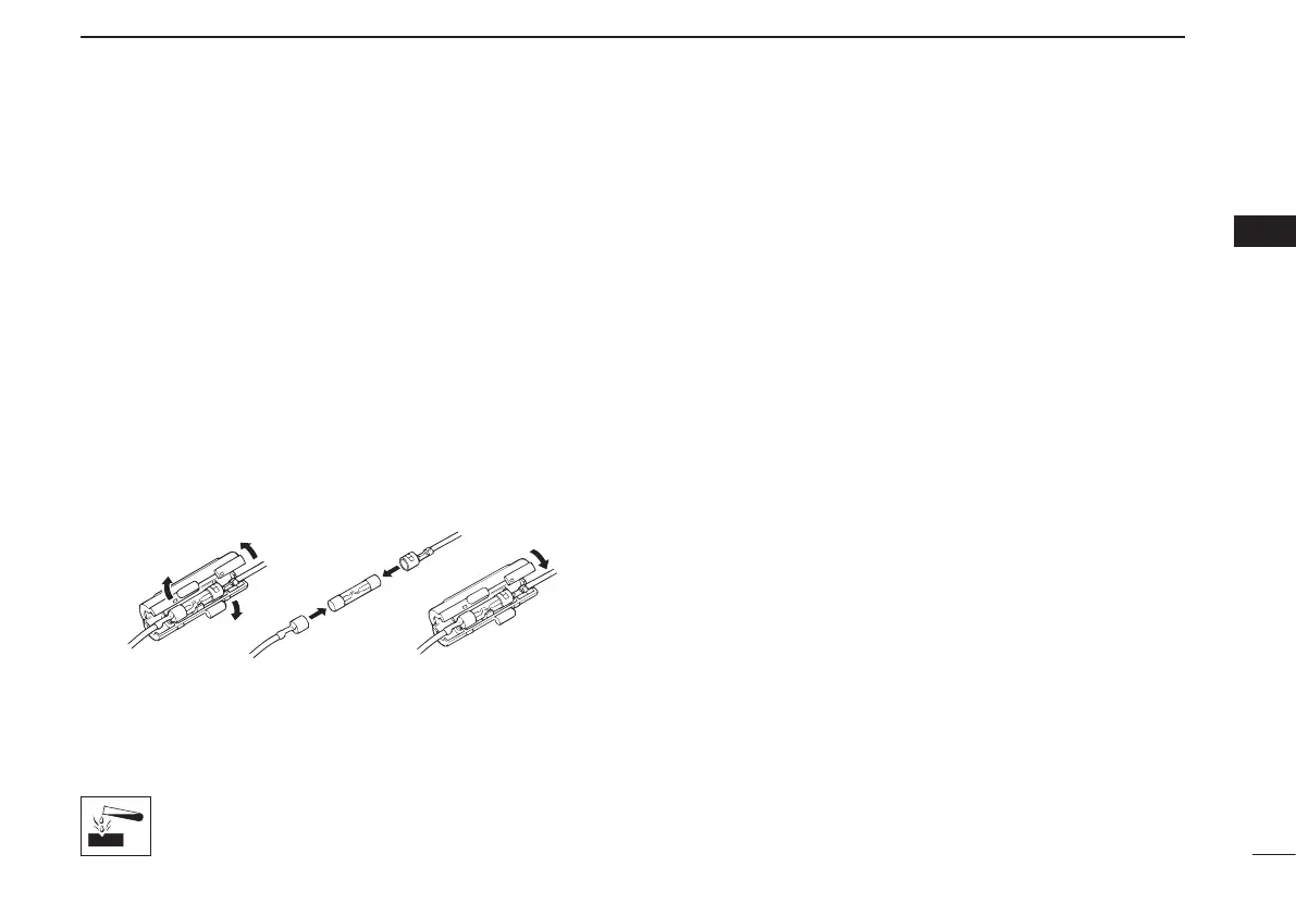
■ Fuse replacement
A fuse is installed in each fuse holder of the supplied DC
power cable*. If a fuse blows or the transceiver stops func-
tioning, track down the source of the problem if possible, re-
pair it and then replace the damaged fuse with a new rated
one.
*Depending on version, only one fuse holder may be attached.
❑Fuserating:10A(foronefuseholder)/20A(forTwofuseholders)
USE the applicable fuse only.
■ Cleaning
If the transceiver becomes dusty or dirty, wipe it clean with a
soft, dry cloth.
DO NOT use harsh solvents such as benzine or
alcohol, as they will damage the transceiver sur-
faces.
■ Options
• OPC-1132A/OPC-347 d c p o w e r c a b l e
Two fuse holders are attached. USE the 20 A fuse only.
OPC-1132A :3m(9.8ft)
OPC-347 :7m(23ft)
• OPC-1939/OPC-2078
a c c c a b l e
Allows you to connect to an external terminal.
OPC-1939 :D-sub15-pin
OPC-2078 :D-sub25-pin
NOTE: No Digital Modulation “IN” using accessory cables.
•HM-152/HM-152T/HM-148G
h a n d m i c r o p h o n e
HM-152 :Handmicrophone
HM-152T :DTMFmicrophone
HM-148G :Selfgroundheavydutymicrophone
•SM-26
d e s k t o p m i c r o p h o n e
•SP-22/SP-30/SP-35 e x t e r n a l s p e a k e r
Inputimpedance:4ø
SP-22/SP-35 :Ratedinput;5W,Max.input;7W
SP-30 :Ratedinput;20W,Max.input;30W
Approved Icom optional equipment is designed for optimal perfor-
mance when used with an Icom transceiver.
Icom is not responsible for the destruction or damage to an Icom
transceiver in the event the Icom transceiver is used with equipment
that is not manufactured or approved by Icom.
 Loading...