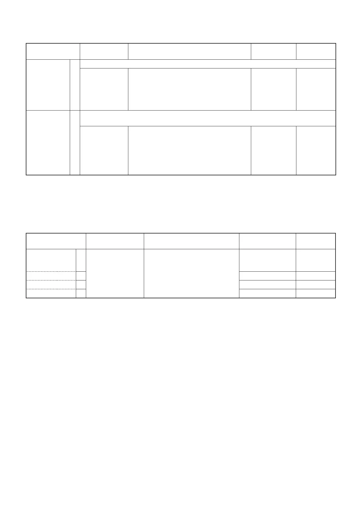
5 - 3
ADJUSTMENT
TRANSCEIVER’S
CONDITION
OPERATION
ADJUSTMENT
ITEM
VALUE
TX OUTPUT
POWER
(High)
1 • CH. : 16
• Transmitting
• Connect an RF power meter to the
antenna connector. [RF Power (High)]
4.5 W
(L_High)* 2 [RF Power (L_High)] 2.5 W
(Low) 3 [RF Power (Low)] 0.75 W
(E_Low)* 4 [RF Power (E_Low)] 0.45 W
*: For only [FRG] version.
5-4 TRANSMIT ADJUSTMENTS
1) Select an adjustment item using [
↑
]/[
↓
] on the PC's keyboard.
2) Set or modify the adjustment value as specifi ed using [
←
]/[
→
] on the PC's keyboard, then push [ENTER].
ADJUSTMENT
TRANSCEIVER’S
CONDITION
OPERATION
ADJUSTMENT
ITEM
VALUE
RX SENSITIVITY
1 NOTE: When "RX SENSITIVITY" is re-adjusted, "SQUELCH" must be re-adjusted too.
• CH. : 16
• Receiving
• Connect an SSG to the antenna connector and
set it as;
Frequency : 156.800 MHz
Level
†
: +30 dBµ (–77 dBm)
Modulation : 1 kHz
Deviation : ±3.0 kHz
[BPF]
Push [ENTER]
on [BPF].
(Automatic
adjustment)
SQUELCH 1 NOTE: When "RX SENSITIVITY" must be adjusted before "SQUELCH." And when "RX SENSITIVITY" is
re-adjusted, "SQUELCH" must be re-adjusted too.
• CH. : 16
• Receiving
• Connect an SSG to the antenna connector and
set it as;
Frequency : 156.800 MHz
Level
†
:
–4 dBµ
(–111 dBm)
[M24] and [AUS]
–3 dBµ
(–110 dBm)
[M23] except [AUS]
Modulation : 1 kHz
Deviation : ±3.0 kHz
[Noise]
Push [ENTER]
on [Noise].
(Automatic
adjustment)
†
; The output level of the standard signal generator (SSG) is indicated as the SSG’s open circuit.
5-3 RECEIVE ADJUSTMENTS
1) Select an adjustment item using [
↑
]/[
↓
] on the PC's keyboard.
2) Set or modify the adjustment value as specifi ed using [
←
]/[
→
] on the PC's keyboard, then push [ENTER].

 Loading...