3 - 1
SECTION 3
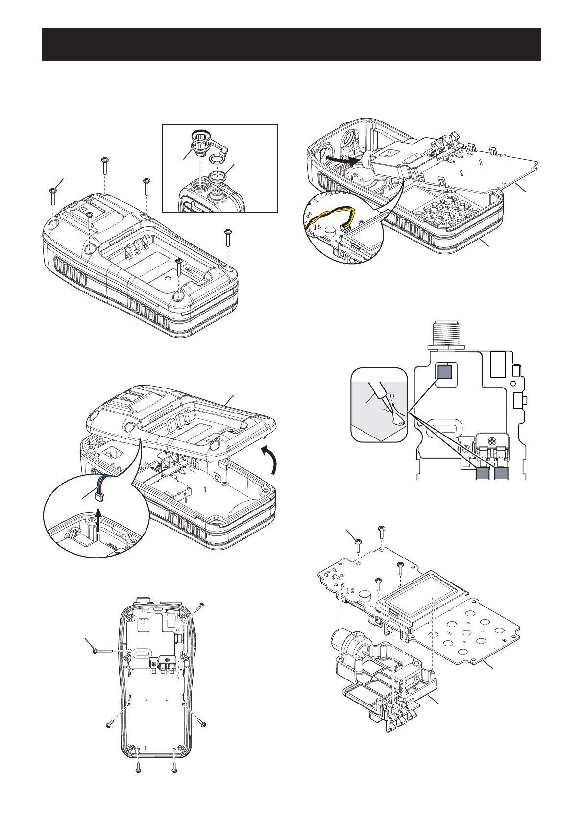
DISASSEMBLY INSTRUCTION
1. REMOVING THE PCB
1) Remove the battery pack from the transceiver.
2) Remove the DC cap and antenna nut.
3) Remove 6 screws from the rear panel.
2. REMOVING THE CHASSIS
1) Unsolder 3 points shown.
4) CAREFULLY lift the rear panel up and unplug the
wet sensor wire.
2) Remove 4 screws from the PCB, and then remove
the CHASSIS.
5) Remove 6 screws from the PCB.
DC cap
Antenna nut
6 screws
Rear panel
Wet sensor
wire
6 screws
Front panel
PCB
SP cable
UNSOLDER
Solder
remover
Chassis
4 screws
Chassis
PCB
6) CAREFULLY lift the PCB out of the front panel, and
then turn it over in order to unplug the speaker wire.
(Continued on the right above.)
 Loading...