4 - 5
Pin Port
Description
number name
Pin Port
Description
number name
2
3
4
6
7
8
9
12
13
18
22
23
24
30
31
40
41
42
43
44
45
KEYM
TXDET
SQLV
PCK
PDATA
WXDEC
DSCENC
BEEP
PSTB
ECK
DSCDEC
UNLK
EDATA
SQL
PTT
SCAN
CH/WX
CH16
DN
UP
DSC
Input port for the HM-141 key signals.
Input port for the transmit detecting
signal.
High: While transmitting.
Input port for the squelch volume sig-
nal.
Outputs the clock signal to the PLL IC
(MAIN unit; IC8, pin 4).
Outputs data signals to the PLL IC
(MAIN unit; IC8, pin 5).
Input port for the WX alert decode sig-
nal.
Outputs the DSC encode signal.
Outputs beep audio signals.
High: While sounds beep audio.
Outputs strobe signals.for the PLL IC
(MAIN unit; IC8, pin 3).
Outputs the clock signal to the EEP-
ROM (IC4, pin 6).
Input port for the DSC decode signal.
Input port for the PLL unlock signal.
Low: While the PLL is unlocked.
I/O port for the EEPROM data signal.
Input port for the squelch level signal.
Input port for the HM-141 PTT switch.
Low: While the PTT switch is
pushed.
Input port for the SCAN switch.
Low: While the [SCAN] switch is
pushed.
Input port for the [CH/WX] switch.
Low: While the [CH/WX] switch is
pushed.
Input port for the [CH16] switch.
Low: While the [CH16] switch is
pushed.
Input port for the [
√] switch.
Low: While the [
√] switch is pushed.
Input port for the [
∫] switch.
Low: While the [∫] switch is pushed.
Input port for the [DSC] switch.
Low: While the [DSC] switch is
pushed.
46
47
49
50
51
52
53
54
62–88
92–95
Input port for the [Distress] switch.
Low: While the [Distress] switch is
pushed.
Outputs the microphone muting circuit
(IC7) control signal.
Low: While transmitting the DSC sig-
nal.
• Outputs the transmit power control
signal.
• Outputs the receiver RF attenuator
control signal.
Low: While the attenuator is ON.
Outputs the receiver mute control sig-
nal.
Low: While muting.
Outputs the transmitter mute control
signal.
High: While muting.
Outputs the T5 regulator (MAIN unit;
Q31, Q32) control signal.
High: While transmitting
Outputs the R5 regulator (MAIN unit;
Q33, Q34) control signal.
High: While receiving.
Outputs special alarm audio signals
(ex. when receiving distress signal).
Low: While sounds special alarm.
Output LCD segment signals.
Output LCD common signals.
DTRS
PTTC
H/L
RMUTE
TMUTE
SEND
RCV
BPLVL
SEG1–
SEG27
COM3–
COM0
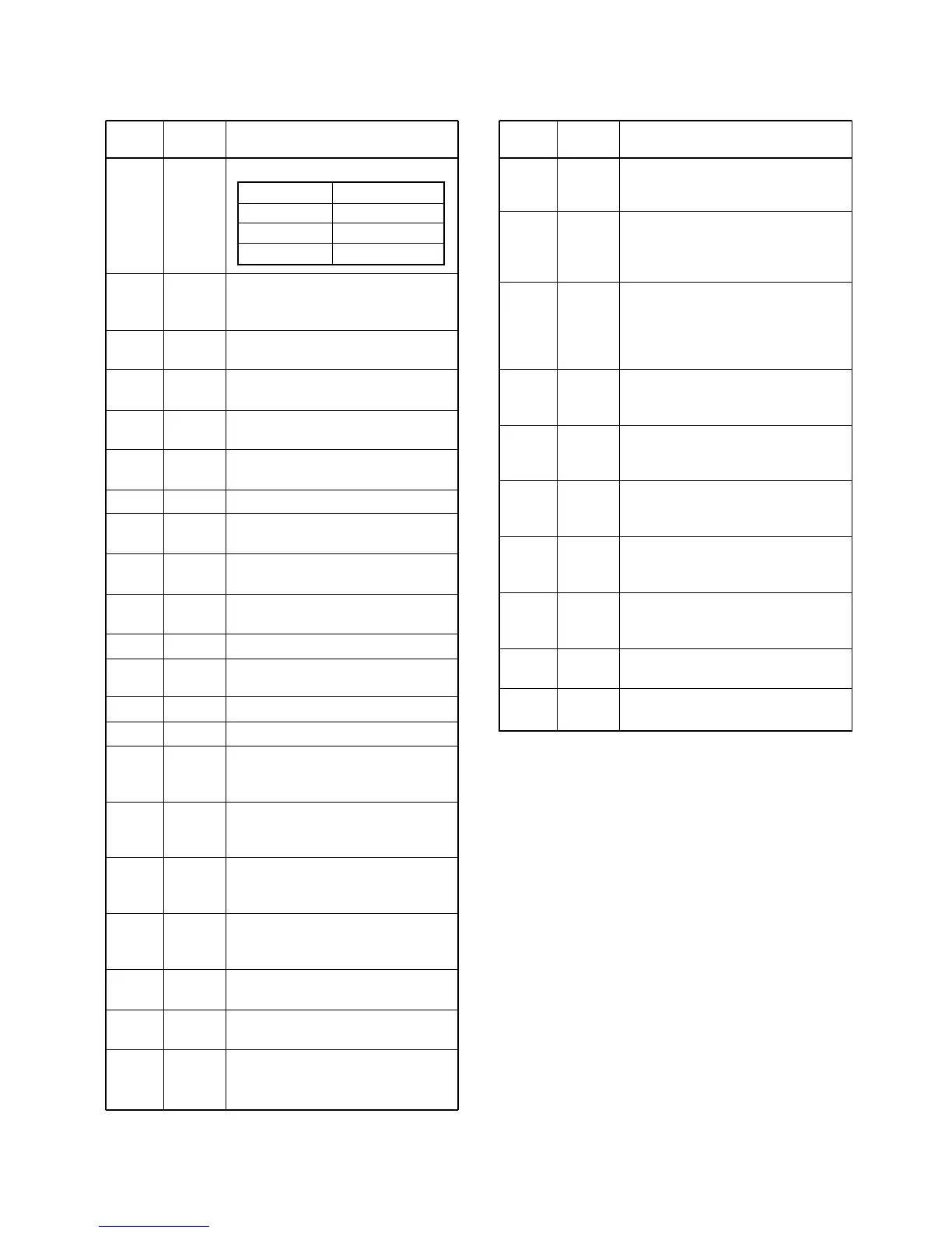
4-7 PORT ALLOCATIONS
4-7-1 CPU (LOGIC BOARD; IC1)
Pushed key Input voltage
[∫] 2.02 V ±0.12 V
[
√] 3.00 V ±0.13 V
[Hi/Lo] 3.84 V ±0.10 V

 Loading...