4 - 1
SECTION 4 CIRCUIT DESCRIPTION
4-1 RECEIVER CIRCUITS
4-1-1 ANTENNA SWITCHING CIRCUIT
(MAIN UNIT)
The antenna switching circuit functions as a low-pass filter
while receiving and as resonator circuit while transmitting.
The circuit does not allow transmit signals to enter receiver
circuits.
Received signals enter the MAIN unit from the antenna con-
nector and pass through the low-pass filter (L1, L2, C3–C5).
The signals are then applied to the RF circuit via the anten-
na switching circuit (D2).
4-1-2 RF CIRCUIT (MAIN UNIT)
The RF circuit amplifies signals within the range of frequen-
cy coverage and filters out-of-band signals.
The signals from the antenna switching circuit pass through
the *attenuator (R2, C9) and a tunable bandpass filter (D4,
L6, C12–C15) where the object signals are led to the RF
amplifier circuit (Q1).
(*Passing through the attenuator is [#10] ONLY.)
The amplified signals at Q1 are applied to other tunable
bandpass filter (D5–D7, L8, L9, C23–C26, C28–C32) to sup-
press unwanted signals and improve the selectivity. The sig-
nals are then applied to the 1st mixer circuit.
4-1-3 1ST MIXER AND 1ST IF CIRCUITS
(MAIN UNIT)
The 1st mixer circuit converts the received signal to a fixed
frequency of the 1st IF signal with a 1st LO (VCO output) fre-
quency. By changing the 1st LO frequency, only the desired
frequency will be passed through two crystal filters at the
next stage of the mixer.
The signals from the RF circuit are mixed with the VCO sig-
nals at the 1st mixer circuit (Q2) to produce a 21.7 MHz 1st
IF signal.
The 1st IF signal is applied to two crystal filters (FI1, FI2) to
suppress out-of-band signals and is then amplified at the IF
amplifier (Q4). The amplified signal is applied to the 2nd
mixer circuit (IC1).
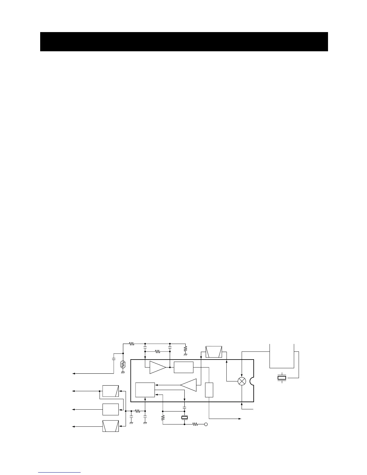
4-1-4 2ND IF AND DEMODULATOR CIRCUITS
(MAIN UNIT)
The 2nd mixer circuit converts the 1st IF signal to a 2nd IF
signal. A double superheterodyne system (which converts
receive signals twice) improves the image rejection ratio and
obtains stable receiver gain.
The FM IF IC (IC1) contains the 2nd local oscillator, 2nd
mixer, limiter amplifier, quadrature detector, and noise
detector circuits, etc.
The 1st IF signal from Q4 is applied to the 2nd mixer section
of IC1 (pin 16), and is mixed with a 21.25 MHz 2nd LO sig-
nal generated at the PLL circuit using the reference fre-
quency (21.25 MHz) to produce a 450 kHz 2nd IF signal.
The 2nd IF signal from IC1 (pin 3) is passed through the
ceramic filter (FI3), where unwanted signals are sup-
pressed, and is then applied to the 2nd IF (limiter) amplifier
in IC1 (pin 5). The signal is applied to the FM detector sec-
tion in IC1 for demodulation into AF signals.
The FM detector circuit employs a quadrature detection
method (linear phase detection), which uses a ceramic dis-
criminator (X1) for phase delay to obtain a non-adjusting cir-
cuit. The detected signal from IC1 (pin 9) is applied to the AF
circuit.

 Loading...