84
10
CONNECTIONS AND MAINTENANCE
r DC POWER CONNECTOR
Connects to a 13.8 V DC power source.
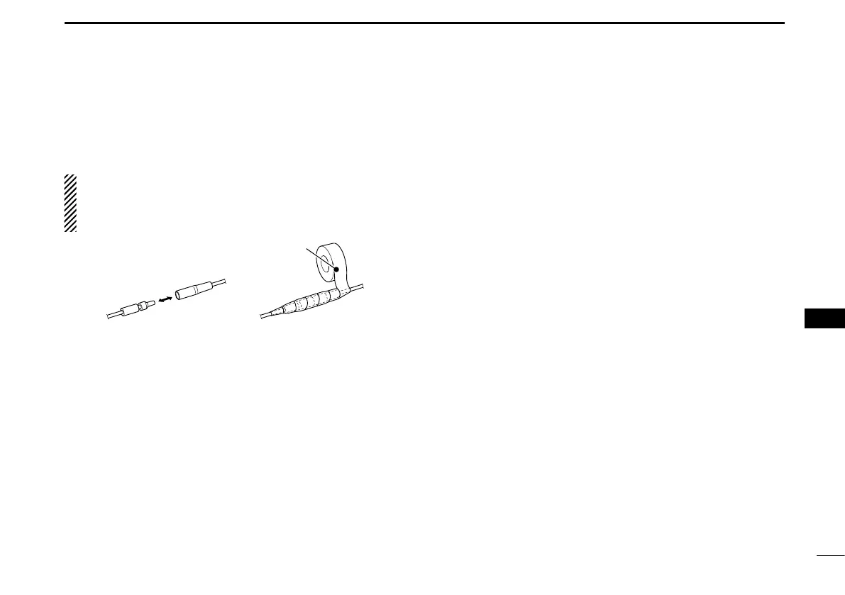
CAUTION: After connecting the DC power cable, NMEA
leads, external speaker leads and PA speaker leads, cover
the connector and leads with an adhesive tape, as shown
below, to prevent water seeping into the connection.
t GROUND TERMINAL
Connects to a vessel ground to prevent electrical shocks
and interference from other equipment occurring. Use a
PH M3 × 6 screw (not supplied).
y COMMAND MICROPHONE JACK
Connects to the optional Command microphone. (p. 88)
Connect to the MA-500TR D
Connect the transceiver to the high-density D-Sub 15-pin
connector of the MA-500TR using the OPC-2014* cable. Af-
ter connecting, an Individual DSC call can be made to the
AIS target using the transponder without entering the target’s
MMSI code.
* The OPC-2014 is supplied with the MA-500TR
• Listener A (Data-H) lead (Yellow):
Connects to lead 3 of the OPC-2014.
• Listener B (Data-L) lead (Green):
Connects to lead 2 of the OPC-2014.
• Talker A (Data-H) lead (White):
Connects to lead 5 of the OPC-2014.
• Talker B (Data-L) lead (Brown):
Connects to lead 4 of the OPC-2014.
1
2
3
4
5
6
7
8
9
10
11
12
13
14
15
16
 Loading...