4-3
• TX AMP CIRCUITS
• MIC AMP CIRCUITS
• TX AF CIRCUITS
• MODULATION CIRCUITS
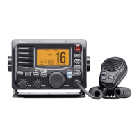
MODULATION CIRCUITS (MAIN UNIT)
The MIC signal from the TX AF circuits is applied to the VCO
(Q3, Q4 and D2–D4). The modulation signal is applied to D2,
to obtain Frequency Modulation.
The modulated VCO output signal is passed through the buf-
fers (Q5 and Q7), and then applied to the TX AMP circuits as
a TX signal, through the LO SW (D7).
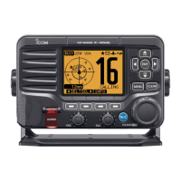
TX AMP CIRCUITS (MAIN UNIT)
The TX signal is amplifi ed by the YGR (Q21) and power AMP
(IC1), and then passed through the TX output power detec-
tor (D12 and D13), ANT SW (D14), and LPF (L22, L23 and
C104–C106), before being sent to the antenna.
APC CIRCUITS (MAIN UNIT)
The voltage produced at the LPF (L21, C101 and C102) is
rectifi ed by D12 and D13, and is used as the TX power sens-
ing voltage.
The voltage is applied to the APC AMP (IC2, pin 3), and the
output voltage controls the gate bias voltage of power AMP
(IC1) to keep the TX output power constant.
4-2 TRANSMIT CIRCUITS
TX AF CIRCUITS (MAIN UNIT)
The AF signal from the microphone (MIC signal) is passed
through the MIC mute SW (IC502, pins 1, 2), and then ap-
plied to the MIC AMP (IC513, pin ).
The MIC signal from the HM-195/HM-205RB is passed
through the ATT (R531 and R532), MIC mute SW (IC502B,
pins 4, 3), and then applied to the MIC AMP (IC513, pin ).
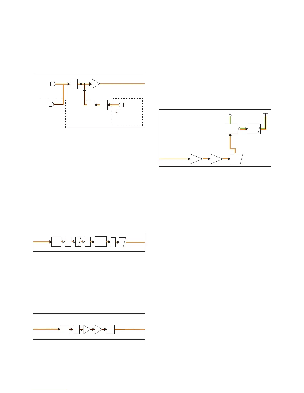
TX AF CIRCUITS (MAIN UNIT)
The amplifi ed MIC signal is applied to the noise canceller IC
(IC901, pin 28).
The processed MIC signal is output from pin 36, passed
through the AF SW (IC505, pins 8, 9), and then applied to the
D/A converter (IC19, pin 22) to be adjusted in level.
The level-adjusted AF signal is output from pin 23, and
passed through the AF MUTE SW (IC882, pins 8, 9), and
then applied to the IDC AMP (IC513B, pin 6), which limits the
amplitude of MIC signal to prevent the over deviation. The
amplitude-limited signal is output from pin 7, and passed
through the LPF (IC513C, pins 10, 8), and then applied to the
modulation circuits.
HM-195/HM-205RB
HM-205B
HM-195
AF
MUTE
MIC
AMP
AF
MUTE
ATT
MIC-IN
MAIN UNIT
FRONT UNIT
IC513A
To the TX AF circuits
IC502
IC502B
OPTIONAL
COMMANDMIC
TX/RX
SW
D7,D8:
BUFF
BUFF
VCO
From the
TX AF circuits
To the
TX AMP circuits
Q5D3,D4
SHIFT
Q2
D1
Q7
Q8
ANT
LPF
ANT
SW
YGR
AMP
PWR
AMP
LPF
Q21
D14,D15
IC1:
D16
From the modulation
circuits
RX circuits
Pre-
emphasys
LPF
D/A
From the
MIC AMP circuits
To the modulation
circuits
IC513C
NOISE
CANCELLER
IC901
IC505D
AF
AF
MUTE
SW
I
C882C
IC19
IC513B
IDC
 Loading...