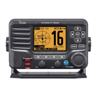
DISASSEMBLY INSTRUCTION
1. Removing the LOGIC UNIT
1) Unscrew 14 screws from the rear panel, and
remove the front panel.
2) Disconnect the fl at cables and speaker cable.
BE CAREFUL when you disassemble the front cover
from the tranceiver body. Otherwise the speaker cable
and the fl at cable may be cut.
FLAT
CABLE
INLINE
CABLE
FRONT PANEL
J1
J2
J8
J3
J4
REAR PANEL
SCREWS
FRONT PANEL
LOGIC UNIT
UNSOLDER
Solder
remover
FRONT PANEL
SCREWS
LOGIC UNIT
3) Unscrew 10 screws from the LOGIC UNIT.
4) Unsolder 12 points.
5) Take off the LOGIC UNIT from the front panel.
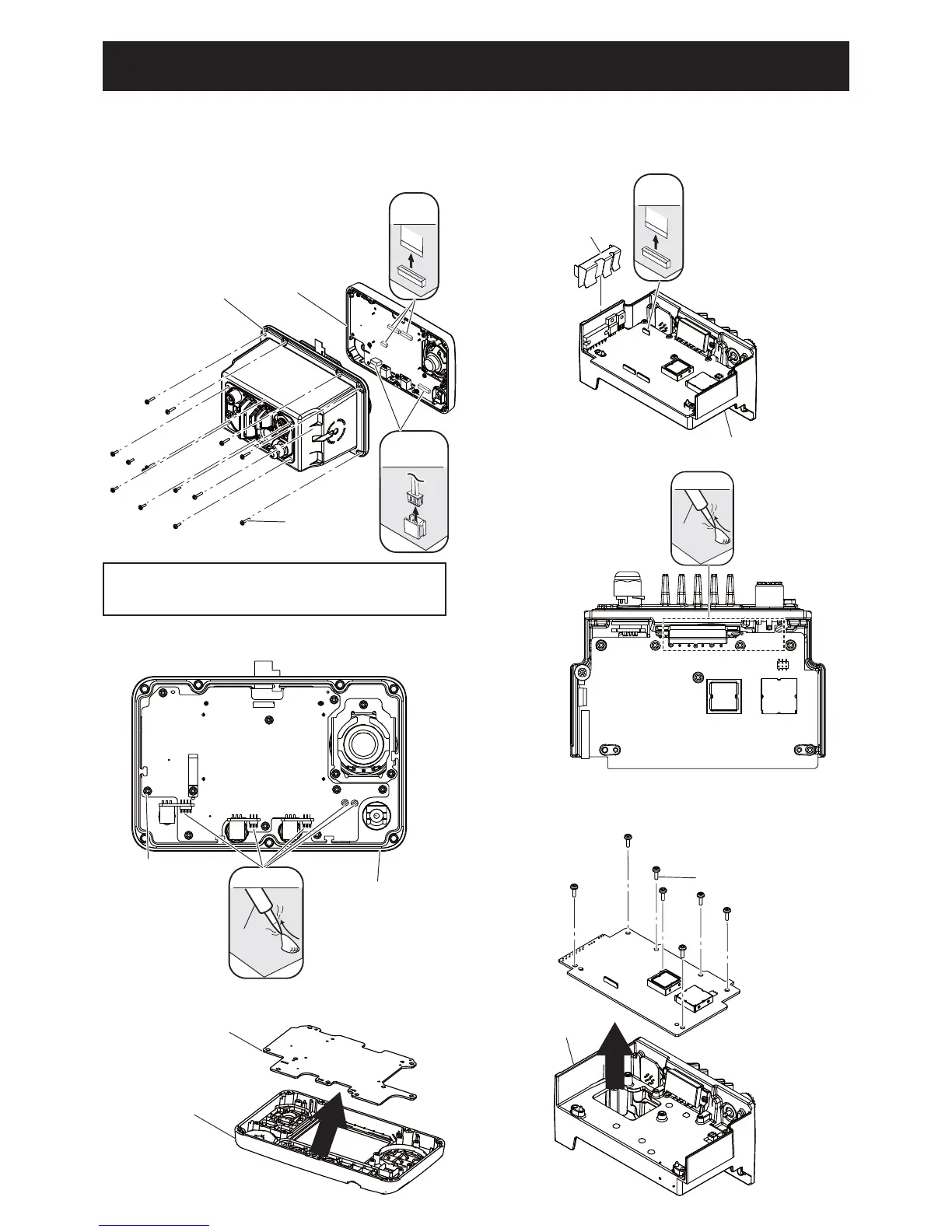
2. Removing the MAIN UNIT
1) Remove IC CLIP.
2) Disconnect the fl at cable.
3) Unsolder 11 points.
UNSOLDER
Solder
remover
MAIN UNIT
CHASSIS
SCREWS
MAIN UNIT
FLAT
CABLE
IC CLIP
J4
CHASSIS
MAIN UNIT
4) Unscrew 7 screws from the MAIN UNIT.
5) Take off the MAIN UNIT from the CHASSIS.
 Loading...