4-4
• FREQUENCY SYNTHESIZER CIRCUITS
• AIS RECEIVE CIRCUITS
• NMEA2000 DATA ROUTUNG CIRCUITS
4-3
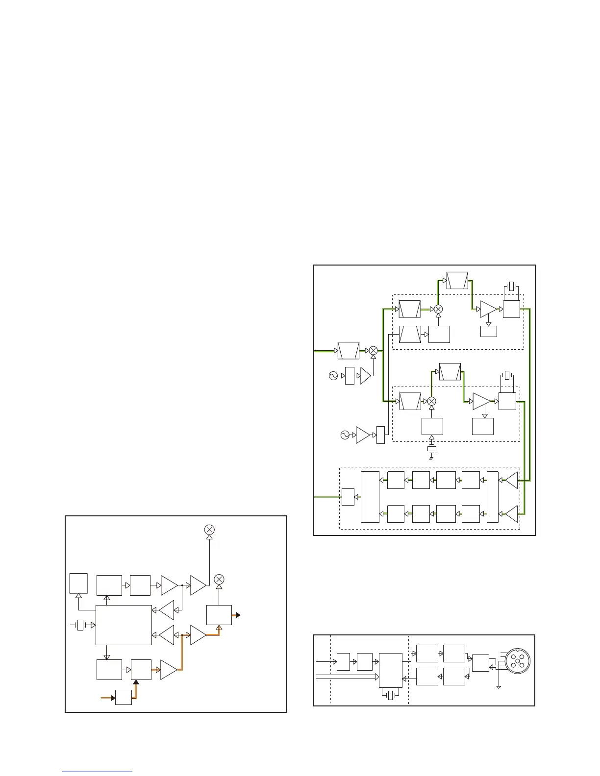
FREQUENCY SYNTHESIZER (MAIN UNIT)
• VCOs
TX VCO
The TX VCO (Q3, Q4 and D2–D4) generates both the TX
signal and 1st LO signal for CH70.
While receiving, the LO signal is applied to the 1st IF mixer
for CH70 (Q302), through the LO SW (D8) and LPF (L66, L65
and C393).
While transmitting, the LO signal is applied to the TX AMP
circuits, through the LO SW (D7).
RX VCO
The RX VCO (Q72 and D51–D53) generates the 1st LO sig-
nal for MAIN channels.
The LO signal is applied to the 1st IF mixer for MAIN chan-
nels (D202), through the LPF (L221, L222 and C262).
• PLL
TX VCO
A portion of VCO output signal is passed through two buffers
(Q5 and Q6), and then fed back to the PLL IC (IC101, pin 1),
through the ATT (R33–R35) and LPF (L8, C74 and C75).
RX VCO
A portion of VCO output signal is passed through two buf-
fers (Q74 and Q75), and then fed back to the PLL IC (IC101,
pin 16), through the ATT (R47–R49) and LPF (L6, C77 and
C78).
The PLL IC (IC101) phase-compares the outputs of the refer-
ence frequency oscillator (TCXO: X101) and VCO, and the
phase-difference is output as the charge pump current.
The current is passed though the loop fi lter (TX VCO: R1–R3,
C1–C3, and C10, RX VCO: R161, R171, C156–C158) to be
converted into the lock voltage that controls the oscillating
frequency of VCO.
When the oscillation frequency drifts, its phase changes from
that of the reference frequency, causing a lock voltage change
to compensate for the drift in the VCO oscillating frequency.
To the TX AMP
circuits
From the TX AF
circuits
BUFF
BUFF
X101
21.25MHz
BUFF
FIL
LOOP
TX/RX
SW
BUFF
BUFF
BUFF
FIL
LOOP
PLL IC
TX VCO
IC101
Q3,Q4
Q5
Q6
D7,D8
D2-D4
SHIFT
Q2
D1
MOD
Q302
Q7
Q8
RX VCO
Q74
Q76
Q75
D51-D53
Q72
D202
1st mixer(MAIN ch)
1st mixer(CH70)
134.825 MHz
CH70 1st Lo frequency:
[USA],[AUS]
Other than [USA],[AUS]
1st Lo frequency range:
125.850-133.275 MHz
125.900-133.125 MHz
IC301
IF IC
4-4
AIS RECEIVER (AIS UNIT: UX-231)
The RX signal from the RF AMP (Q101) is applied to the AIS
UNIT, through J5 on the MAIN UNIT of IC-M506.
The applied signal is passed through the SAW fi lter (FI1) and
applied to the 1st mixer (Q1), and mixed with the 123.175 MHz
1st LO signal, resulting in the 1st IF signal (38.85 MHz for
AIS 1, 38.8 MHz for AIS 2).
The 1st IF signal is applied to the IF ICs (IC1 for AIS 1, IC2 for
AIS 2), and mixed with the 2nd LO signal (38.4 MHz for AIS 1,
38.35 MHz for AIS 2), resulting in the 450 kHz 2nd IF signal.
The 2nd IF signal is passed through the 2nd IF fi lter (FI4 for
AIS 1, FI7 for AIS 2) to remove the sideband noise. The fi l-
tered signal is amplifi ed by the 2nd IF AMP, and demodulated
by the quadrature detector with discriminator (X2 for AIS 1,
X4 for AIS 2).
The demodulated AF signal is applied to the AIS baseband
processor (IC8). The processed AIS data is applied to the IC-
M506, through J5 on the MAIN UNIT of IC-M506.
X3
2NDIF
AMP
BPF
XTAL
BPF
CERAMIC
BPF
2ND LO
BUFF
FM
DET
BPF
XTAL
BPF
CERAMIC
FM
DET
2NDIF
AMP
2ND LO
BUFF
AMP
AMP
X2AMP
BRF
AMP
X2
X4
X3
41.0583 MHz
123.175 MHz
SAW
450 kHz
RSSI
450 kHz
RSSI
38.850 MHz
38.800 MHz
MUX
GMSK
decode
NRZI
decode
HDLC
decode
Buffer
NMEA
Formter
UART
GMSK
decode
NRZI
decode
Buffer
HDLC
decode
38.400 MHz
19.200 MHz
FI1
Q1
Q2
X1
TCXO
X5
TCXO
IC6
FI2,3 FL-470
FI4
IC1
FI7
IC2
FI5,6 FL-473
IC8
38.350 MHz
Q3
From the IC-M506
To the IC-M506
LEVEL
CONV
PHOTO
COUPLE
PHOTO
COUPLE
CI-V
I/F
12
34
5
J1
1
2
3
4
5
X1
CONNECT UNIT
MAIN UNIT
IC1
ENOLC
3FCI
BUFF
CAN TX
BUFF
CAN RX
BUFF
IC3
Q3
Q4
D1
NM2K DATA
IC6
IC3
IC4
IC5
IC2
4-5
NMEA2000 DATA ROUTING CIRCUITS
(NMEA2000 UNIT: UX-232)
The AIS and GPS position data from the external devices is
sent to the IC-M506, through the NMEA2000 network.
 Loading...