D152,
D153, D172, D173, D213,
D214 and D238 employ
varactor diodes
that are controlled by the
CPU (LOGIC unit;
IC1
)
to
track the bandpass filter.
These varactor diodes tune
the
center frequency of an RF
passband for wide width
receiving and good image
response rejection.
4-1-3
1ST
MIXER AND 1ST IF CIRCUITS {RF
UNIT)
The 1st
mixer circuit converts the received RF
signals
to a
fixed
frequency of the 1st IF
signal with the PLL
output
frequency. By
changing the PLL frequency,
only the desired
frequency will pass
through the band pass
filters
at
the next
stage
of the
1st
mixer.
The
amplified signals are mixed
with
1st
LO signals from the
1st
VCO unit at a 1st
mixer (IC271) to produce 1st
IF signals
(266.7
MHz; 340.0 MHz-999.9999
MHz, 429.1 MHz; 0.5
MHz-339.9999 MHz
and 1
.0
GHz-1
.3
GHz).
The 1st
IF signals are
applied
to
each IF filter
(FI401 for
266.7 MHz IF
signal, FI411 for 429.1 MHz
IF signal)
to
suppress
out-of-band
signals. The 1st IF
signals are
amplified at
the
1st
IF amplifier
(Q421)
and then
applied
to
the 2nd mixer
on the MAIN unit.
•
1st LO
frequency and 1st IF
frequency
Receive
frequency
[MHz]
1st LO
frequency
[MHz]
1st IF frequency
[MHz]
0.5-
339.9999
429.6
-
769.0999 429.1
340.0-
609.9999 606.7
-
876.6999 266.7
610.0-
999.9999
343.3
-
733.2999 266.7
1000.0-
1300.0000
733.3
-
870.9000
429.1
4-1-4
2ND MIXER
AND 2ND IF CIRCUIT
(MAIN
UNIT)
The 2nd
mixer circuit
converts the
1st
IF
signal
to a
2nd
IF
signal.
The 1st
IF signals (266.7
MHz or 429.1 MHz)
from the RF
unit are applied to
the 2nd mixer circuit
(IC11) for mixing
with the 2nd LO
signals
to be
converted
into
a
10.7 MHz
2nd IF
signal. The 2nd IF
signal is applied
to
the IF filter
(Fill)
to
suppress
out-of-band signals, and is then
amplified
at the 2nd
IF amplifier
(Q21
).
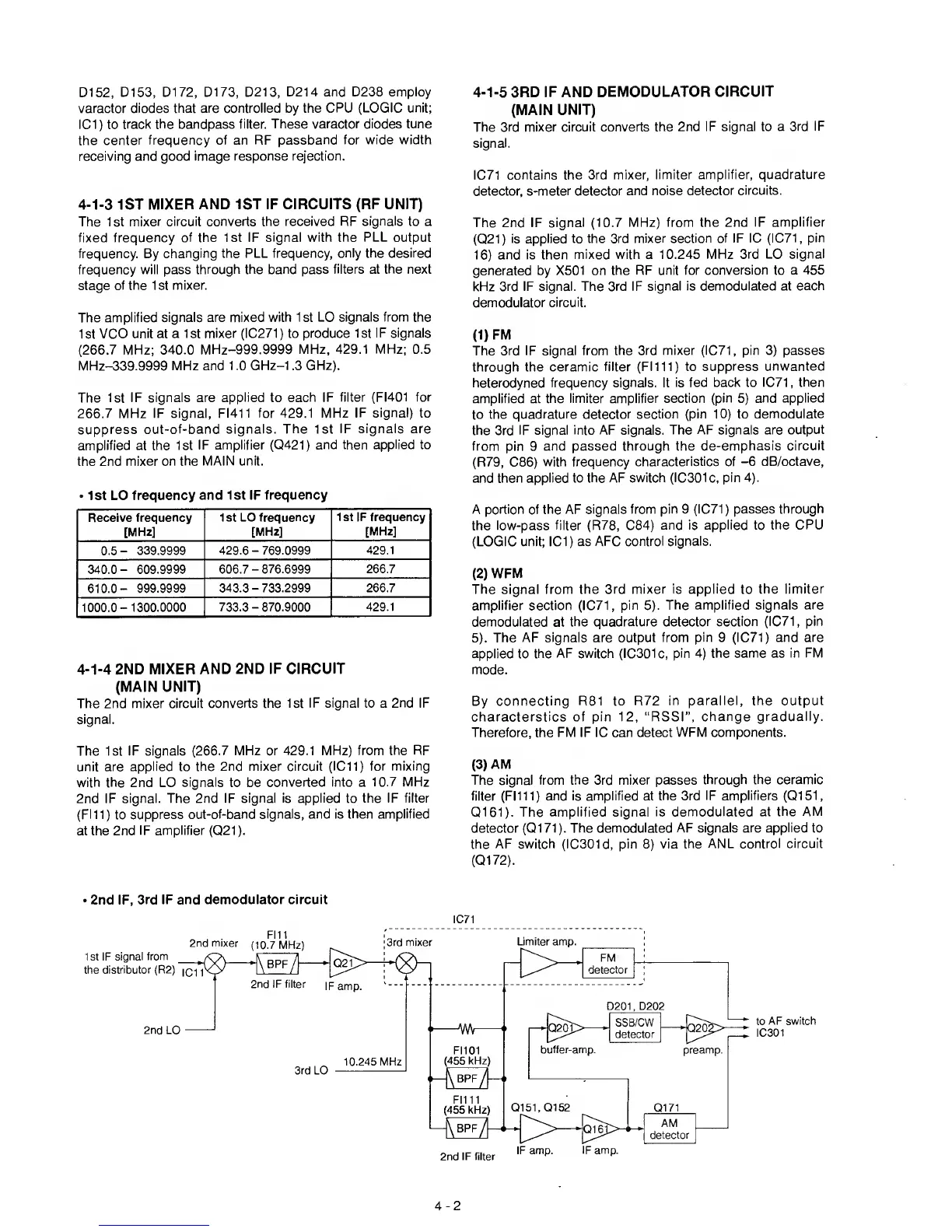
4-1-5
3RD IF AND
DEMODULATOR
CIRCUIT
(MAIN
UNIT)
The
3rd mixer circuit converts
the 2nd IF signal to a
3rd IF
signal.
IC71
contains the 3rd mixer,
limiter amplifier,
quadrature
detector,
s-meter detector and
noise detector circuits.
The 2nd IF signal (10.7
MHz) from the 2nd
IF amplifier
(Q21)
is applied to the 3rd
mixer section of IF 1C (IC71,
pin
16)
and is then
mixed with
a
10.245 MHz
3rd LO signal
generated by X501 on
the RF unit for
conversion
to a
455
kHz
3rd IF signal. The 3rd IF
signal is demodulated at
each
demodulator
circuit.
(1)
FM
The 3rd IF signal from the
3rd mixer
(1071,
pin
3)
passes
through the
ceramic filter (FI111) to
suppress unwanted
heterodyned frequency
signals. It is fed back to
1071,
then
amplified at
the limiter amplifier
section (pin
5)
and applied
to the
quadrature detector section
(pin
10)
to
demodulate
the 3rd IF signal
into AF signals. The AF signals
are output
from pin
9
and passed
through the
de-emphasis circuit
(R79,
086)
with frequency
characteristics of
-6
dB/octave,
and
then applied to the AF
switch
(10301 c,
pin
4).
A
portion of the AF signals
from
pin
9
(1071)
passes
through
the low-pass
filter (R78,
084)
and
is applied to
the OPU
(LOGIO unit;
101)
as
AFO
control
signals.
(2)
WFM
The signal
from the 3rd mixer is applied
to
the
limiter
amplifier section
(1071,
pin
5).
The amplified signals
are
demodulated
at
the quadrature
detector section
(1071,
pin
5).
The
AF signals are output from
pin
9
(1071)
and are
applied
to
the AF switch (10301c,
pin
4)
the same
as
in FM
mode.
By
connecting R81 to R72 in
parallel, the output
characterstics of pin
12,
“RSSI”, change gradually.
Therefore, the FM IF 10 can detect
WFM components.
(3)
AM
The signal from
the
3rd
mixer
passes
through the
ceramic
filter (FI111)
and is amplified at the 3rd
IF amplifiers
(Q151,
Q161).
The amplified
signal is demodulated at the
AM
detector
(Q171).
The demodulated AF signals are
applied
to
the AF switch
(10301 d,
pin
8)
via
the ANL control circuit
(Q172).
•
2nd IF,
3rd IF and demodulator circuit
IC71
to
AF switch
IC301
4-2
 Loading...