4-1
RECEIVER
CIRCUITS
4-1-1
ANTENNA
SWITCHING CIRCUIT (RF
UNIT)
Received
signals enter the
RF unit from the
antenna
connector (J1)
and
pass
through a
limiter (D1) and an
attenuator circuit (D2). The
signals are
then applied
to
the
RF circuit via the
antenna switching circuit (D51,
D151,
D171,
D211, D231)
which suppress out-of-band
signals.
4-1-2
RF CIRCUIT (RF UNIT)
The
RF circuit
amplifies the received
signals within the
range
of frequency coverage and
filters out-of-band
signals.
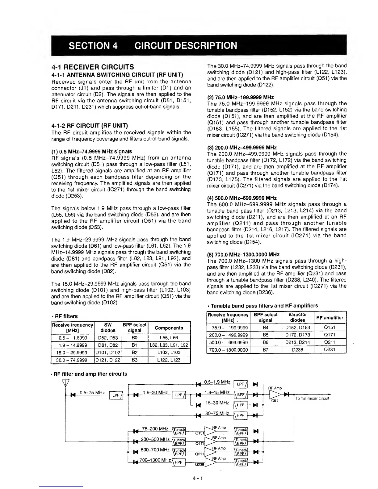
(1)
0.5
MHz-74.9999 MHz
signals
RF
signals
(0.5
MHz-74.9999
MHz) from an
antenna
switching circuit (D51) pass
through a
low-pass filter (L51,
L52).
The filtered
signals are amplified at
an RF amplifier
(Q51)
through each bandpass
filter
depending on the
receiving
frequency. The
amplified signals
are then applied
to
the 1st
mixer circuit (IC271)
through the band
switching
diode
(D253).
The
signals below
1.9 MHz pass
through
a
low-pass filter
(L55, L56)
via the band
switching diode (D52), and
are then
applied to
the
RF amplifier circuit
(Q51)
via the
band
switching
diode (D53).
The
1
.9
MHz-29.9999 MHz
signals
pass
through the band
switching
diode
(D61)
and low-pass
filter (L61, L62). The
1.9
MHz-14.9999
MHz signals pass
through the
band switching
diode (D81)
and bandpass
filter (L82, L83,
L91,
L92),
and
are
then applied to
the RF
amplifier circuit
(Q51)
via
the
band
switching
diode (D82).
The 15.0
MHz-29.9999
MHz signals
pass
through
the
band
switching diode (D101)
and
high-pass filter (LI
02,
LI
03)
and
are then
applied to the RF
amplifier circuit
(Q51)
via the
band
switching
diode (D102).
•
RF
filters
Receive
frequency
[MHz]
sw
diodes
BPF select
signal
Components
0.5-
1.8999 D52, 053 80
L55, L56
1.9-14.9999 D81
,
082 81
L82, L83, L91,
L92
15.0-29.9999 0101, 0102 82
L102, LI 03
30.0
-
74.9999 0121,
0122 83
L122,
L123
The 30,0
MHz-74.9999 MHz
signals pass
through the band
switching diode (D121)
and
high-pass filter (LI
22,
LI
23),
and are
then applied to the
RF
amplifier circuit
(Q51)
via the
band
switching diode (D122).
(2)
75.0
MHz-199.9999
MHz
The 75.0
MHz-199.9999
MHz signals pass
through the
tunable
bandpass
filter
(D152,
LI
52)
via the band
switching
diode (D151), and
are then
amplified
at
the RF
amplifier
(Q151)
and
pass
through
another tunable bandpass
filter
(D153,
LI
55).
The filtered
signals are
applied
to
the 1st
mixer
circuit (IC271) via the
band switching
diode (D154).
(3)
200.0
MHz-499.9999 MHz
The 200.0 MHz-499.9999
MHz
signals pass
through the
tunable
bandpass filter
(D172, LI
72)
via the
band switching
diode (D171),
and are then
amplified at
the RF amplifier
(Q171)
and pass
through
another
tunable
bandpass
filter
(D173, LI
75).
The
filtered signals are
applied to the 1st
mixer circuit (IC27
1 )
via
the band switching
diode (D1
74).
(4)
500.0 MHz-699.9999
MHz
The
500.0 MHz-699.9999
MHz signals pass
through a
tunable band
pass
filter (D213,
L213, L214) via the
band
switching diode (D211), and
are then
amplified at an
RF
amplifier
(Q211)
and
pass
through
another tunable
bandpass
filter
(D214,
L216, L217).
The filtered
signals are
applied to
the
1st
mixer circuit (IC271) via the
band
switching diode (D154).
(5)
700.0 MHz-1300.0000
MHz
The 700.0
MHz-1300 MHz signals pass
through
a
high-
pass
filter (L232,
L233)
via the
band switching diode (D231),
and
are
then amplified at the
RF amplifier
(Q231)
and pass
through
a
tunable
bandpass
filter
(D238, L240). The
filtered
signals
are applied
to
the 1st mixer circuit
(IC271) via the
band switching diode (D236).
•
Tunable band
pass
filters and
RF amplifiers
Receive
frequency
[MHz]
.
BPF select
signal
Varactor
diodes
RF
amplifier
84
0152,
0153
Q151
200.0-
499.9999 85 0172,
0173
Q171
500.0-
699.9999
86
0213,
0214
Q211
700.0-
1300.0000
87 0238
Q231
RF
filter
and
amplifier circuits
 Loading...