SECTION 4 CIRCUIT DESCRIPTION
4-1
RECEIVER CIRCUITS
4·1-1
CONVERTER CIRCUIT (MAIN UNIT)
Input signals
from the ANTENNA CONNECTOR are
switched by
RF
relays RL3 and RL4 on the MAIN UNIT
either
to
through
or
to
the converter
circuit
according
to
receive frequency.
When the receive frequency is 1025-1999.9999MHz,
receive
signals are applied
to
the converter
circuit
for
heterodyning. This
circuit
converts
1025-
1999.9999MHz receive signals
to
25-999.9999MHz.
A HPF
consisting
of
L9
and
CB7-CB9
attenuates
strong interfering
signals in the 200MHz band.
When the receive frequency is higher than 1025MHz,
signals from the ANTENNA CONNECTOR are applied
to
the HPF UNIT. This
unit
consists
of
a HPF and
an
RF
amplifier. The HPF
consists
of
a
strip
line,
c1-
C6,
CB
and
C10-C16.
The HPF attenuates signals
with
frequencies below 1200MHz and prevents
LO
signals
(1
GHz) from leaking through the ANTENNA
CONNECTOR. 01 is an
RF
amplifier
and has a gain
of
approximately
10dB
at 1200MHz.
X1
and
014
oscillate
a frequency
of
55.555MHz.
Output from
014
is
multiplied
by three at
L3-L5,
C31,
C44 and C46 to form a frequency
of
166.66MHz. The
166.66MHz frequency
is
amplified
by 015.
Output
from
015
is
multiplied
by three
at
016
to
form a
frequency
of
500MHz, and then the 500MHz signal
(OdBm) is applied
to
the MAIN DOUBLER UNIT.
In
the MAIN DOUBLER UNIT,
output
from
016
on the
MAIN UNIT is
multiplied
by
two
at 01
to
form a LO
signal (1000MHz,
10dBm)
tor
the double balanced
mixer IC9.
4·1·2 20dB ATTENUATOR CIRCUIT
(RF UNIT)
Receive signals from the MAIN UNIT are applied
to
a
BPF
consisting
of
a
strip
line,
L3
and
C1
~cs.
This
circuit
attenuates signals
that
exit
the passband
of
the BPF.
IC5
switches
receive signals through
or
to
the
attenuator.
The
attenuator
consisting
of
R2~RB
provides attenua-
tion
of
approximately 20dB.
4·1·3
RF
AMPLIFIER CIRCUIT (RF UNIT)
Receive signals are
switched
by diodes
D5,
D11,
D12,
D1B,
D19
and
D25
to
each
RF
amplifier. With fre·
quencies higher than 512 MHz,
RF
relays
RL
1 and
RL2 are used
for
the switching.
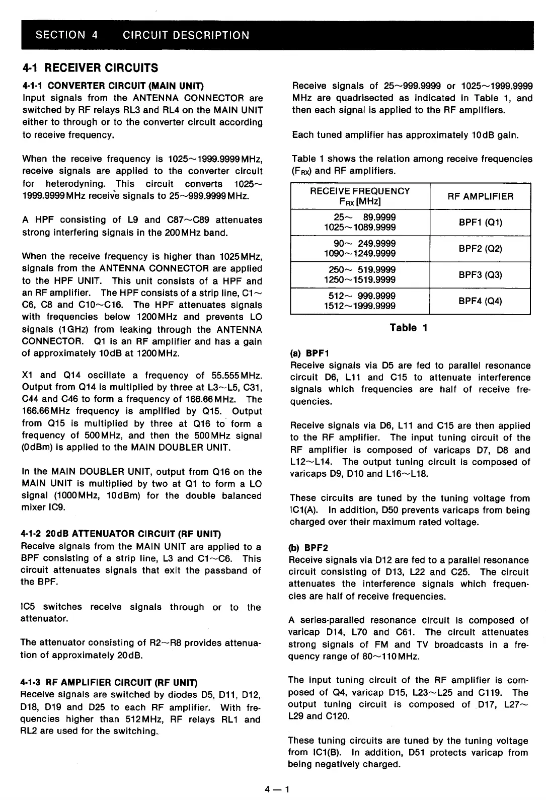
Receive
signals
of
25-999.9999
or
1025-1999.9999
MHz are quadrisected as indicated in Table
1,
and
then each
signal is applied
to
the
RF
amplifiers.
Each tuned
amplifier
has approximately
10dB
gain.
Table 1 shows the relation among receive frequencies
(FRx)
and
RF
amplifiers.
RECEIVE FREQUENCY
RF
AMPLIFIER
FRx[MHz]
25-
B9.9999
BPF1
(01)
1025-10B9.9999
90-
249.9999
BPF2 (02)
1090-1249.9999
250-
519.9999
BPF3 (03)
1250-1519.9999
512~
999.9999
BPF4 (04)
1512-1999.9999
Table 1
(a) BPF1
Receive
signals
via
D5
are fed
to
parallel resonance
circuit
D6,
L
11
and C15
to
attenuate interference
signals which frequencies are
half
of
receive fre-
quencies.
Receive
signals via
D6,
L11
and C15 are then applied
to
the
RF
amplifier. The input tuning
circuit
of
the
RF
amplifier
is composed
of
varicaps
D7,
DB
and
L
12-L
14.
The
output
tuning
circuit
is composed
of
varicaps
D9,
D10
and
L16-L1B.
These
circuits
are tuned by the
tuning
voltage from
IC1(A).
In
addition,
D50
prevents varicaps from being
charged over
their
maximum rated voltage.
(b) BPF2
Receive
signals via
D12
are fed
to
a parallel resonance
circuit
consisting
of
D13,
L22
and
C25.
The
circuit
attenuates the interference signals which frequen·
cies are half
of
receive frequencies.
A
series-paralled resonance
circuit
is composed
of
varicap
D14,
L70 and
C61.
The
circuit
attenuates
strong
signals
of
FM and TV broadcasts in a fre-
quency range
of
B0-110
MHz.
The input tuning
circuit
of
the
RF
amplifier
is com-
posed
of
04,
varicap
D15,
L23~L25
and C119. The
output
tuning
circuit
is
composed
of
D17,
L27-
L29
and C120.
These
tuning
circuits
are tuned by the tuning voltage
from IC1(B). In addition,
D51
protects
varicap from
being
negatively charged.
4-1
 Loading...