EasyManua.ls Logo

Icom IC-R7000 Service Manual

Icom IC-R7000
126 pages
To Next Page IconTo Next Page
To Previous Page IconTo Previous Page
Page #5 background image
1
SECTION 2 OUTSIDE
AND
INSIDE VIEWS
I
2·1
FRONT PANEL
MODE
INDICATOR------.
1 GHz INDICATOR
(1
GHz]
SIG
METER--------------
SCAN-DELAY
CONTROL---
[SCAN-DELA
Y]
METER SWITCH [METER]
SIGNAL INDICATOR [SIG
PROGRAMMED
SCAN-----'
INDICATOR [PRO]
SCAN-SPEED CONTROL
SCAN INDICATOR
[SCAN]------'
[SCAN-SPEED]
VOICE SCAN
CONTROL
SWITCH [VSC]
PHONES
JACK---~
[PHONES]
RECORDING
JACK [REC]
r---SCAN
START/STOP-------,
1
~PRIO
rmPROG n SEL-M MODE MEMORY
l~~Ll!!s~~
I
Eal] Eal]
Eal] Eal]
Eal]
AF GAIN CONTROL [AF
GAIN]-----'
SQUELCH CONTROL
[SQUELCH]-------'
MEMORY CHANNEL SCAN
START/STOP----~
SWITCH [MEMORY]
SELECTED MODE MEMORY SCAN START/STOP
SWITCH
[MODE]
SELECTED MEMORY SCAN START/STOP
SWITCH [SEL-M]
PROGRAMMED SCAN START/STOP
SWITCH
[PROG]
PRIORITY SCAN START/STOP
SWITCH [PRIO]
PRIORITY SCAN SET SWITCH
[PRIO-SET]
PROGRAMMED SCAN SET SWITCH
[PROG-SET]
SELECTED MEMORY SET/RESET SWITCH
[SEL-M-SET/RESET]
DIMMER SWITCH
[DIMMER]
NOISE
BLANKER
SWITCH [NB]
ATTENTUATOR--+ll!;~ll
SWITCH [ATT]
REMOTE
SWITCH
[REMOTE]
-----FREQUENCY
INDICATOR
----AUTO
INDICATOR [AUTO]
MEMORY
CHANNEL
INDICATOR
[M
ch]
'-----SELECTED
MEMORY
INDICATOR
[.]
'-------HI-LO
INDICATOR [HI] [LO]
REMOTE CONTROL SENSOR AND
LED
INDICATOR
c)
I]
TUNING STEP SELECTOR
CONTROL [TS]
MEMORY CHANNEL-WRITE
SWITCH
[MEMORY CH-WRITE]
'----CLEAR
SWITCH [CLEAR]
'----MEMORY
CHANNEL SELECTOR
CONTROL [MEMORY CH]
1 GHz BAND SWITCH
[1GHz)
l~~---SPEECH
SWITCH
[SPEECH]
DIAL LOCK SWITCH
[LOCK]
SELECTED MEMORY
CLEAR
SWITCH-----'
[SEL-M-CL]
TUNING CONTROL
AUTO-WRITE MEMORY SCAN START/STOP SWITCH
[AUTO-M]
2-1

Other manuals for Icom IC-R7000

Question and Answer IconNeed help?

Do you have a question about the Icom IC-R7000 and is the answer not in the manual?

Icom IC-R7000 Specifications

General IconGeneral
BrandIcom
ModelIC-R7000
CategoryReceiver
LanguageEnglish

Summary

ICOM IC-R7000 Service Manual

Section 2 Outside and Inside Views

2-1 Front Panel

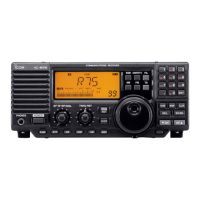
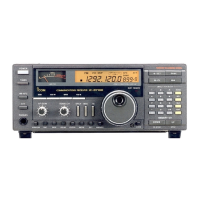
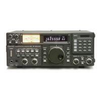
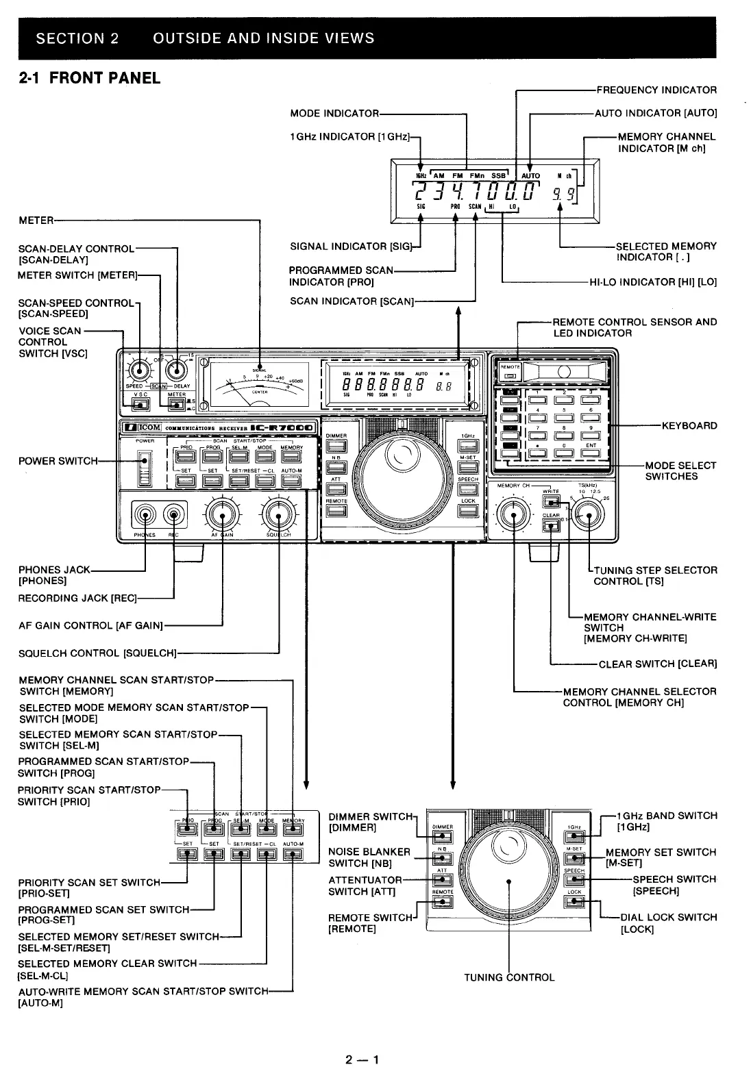
Details the front panel controls and indicators of the IC-R7000 receiver.

Section 4 Circuit Description

4-1 Receiver Circuits

Details the various stages and components involved in receiving signals.

4-1-1 Converter Circuit (Main Unit)

Describes the signal conversion circuit for frequency heterodyning.

4-1-3 RF Amplifier Circuit (RF Unit)

Describes the RF amplifier circuits responsible for boosting signal gain.

4-1-6 1st LO and 1st Mixer Circuits (RF Unit)

Explains the circuits for the first local oscillator and mixer stages.

4.3 PLL Circuit (PLL Unit)

Describes the Phase Locked Loop circuit for generating oscillator signals.

4.4 Logic Circuit (Logic Unit)

Explains the functions of the CPU and associated logic circuits.

Section 6 Maintenance and Adjustment

6-1 Preparation Before Servicing

Lists essential steps and precautions before starting any servicing.

6-2 PLL Adjustment

Details the procedures and settings for adjusting the PLL circuits.

6-3 Local Oscillator Adjustment

Describes how to adjust the local oscillator circuits for proper frequency generation.

6-4 Receiver Adjustment

Provides steps for adjusting the receiver's performance parameters.

Section 9 Voltage Diagram

9-1 IC-R7000

Provides the voltage diagram for the main IC-R7000 unit.

Related product manuals