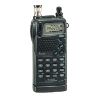
SECTION 3 DISASSEMBLY INSTRUCTIONS
3 - 1
•
DISASSEMBLING PANELS
1 Unscrew 4 screws, A from the rear panel and 2 screws, B
from the rear plate to separate front and rear panels.
2 Unscrew 4 screws, C from the rear plate to remove it.
•
REMOVING LOGIC UNIT
1 Unscrew 4 screws, D from the LOGIC Unit.
2 Unsolder jumper wires from the speaker as shown below.
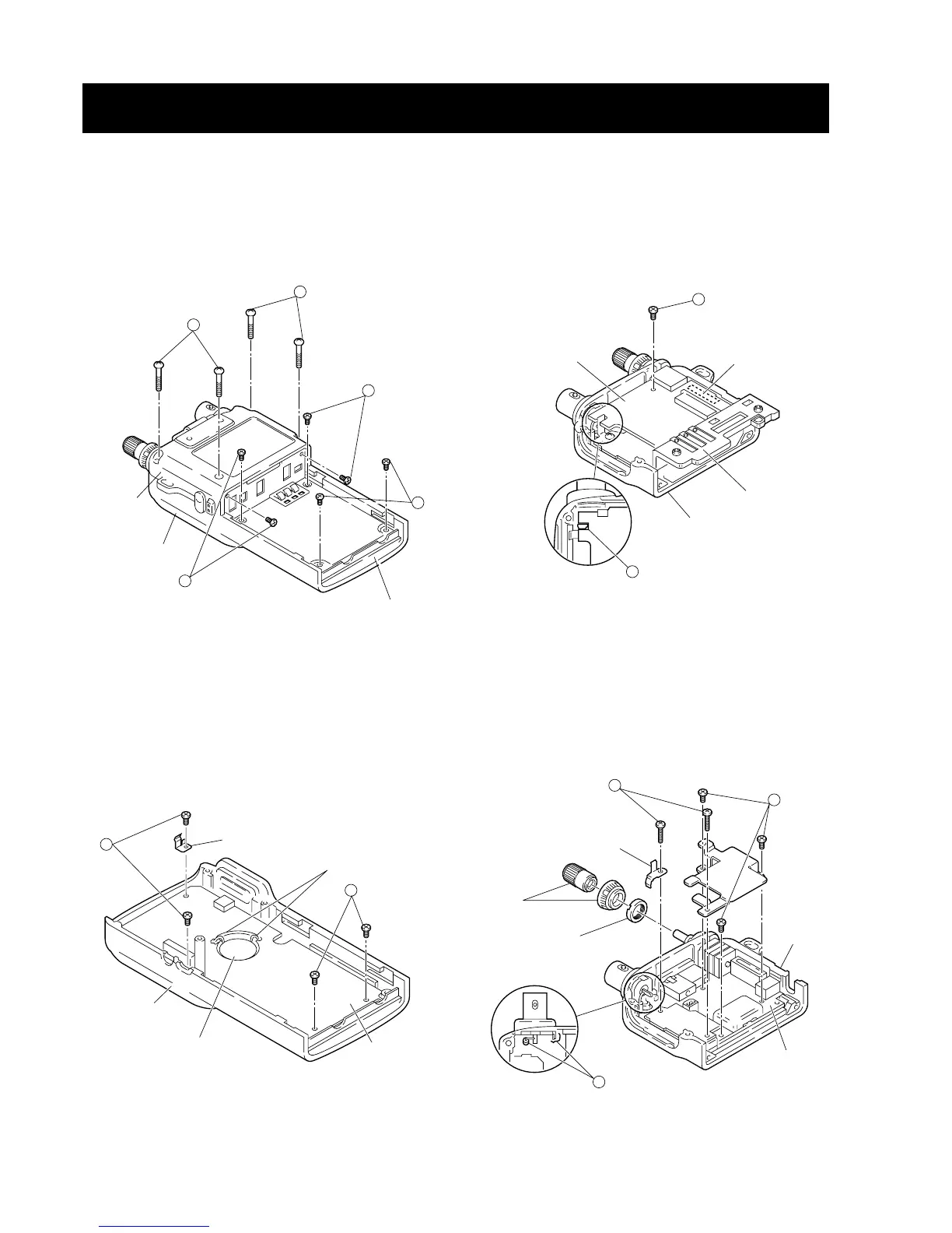
•
REMOVING 2F UNIT
1 Unscrew 1 screw, E from the 2F unit.
2 Unsolder the point, F, then remove the 2F unit with the
contact base.
(Disconnect J1 on reverse side of the 2F unit to remove).
•
REMOVING 1F UNIT
1 Pull the 2 knobs off and then unscrew the nut.
2 Unscrew 3 screws, G and 2 screws, H from the 1F unit.
3 Unsolder 2 points, I then remove the 1F unit.
 Loading...