41
SERVICING
icos system - Installation and Servicing
53
CLEANING THE HEAT EXCHANGER
Reassemble the boiler in the following order:
1. Refit the condensate 'S' trap, ensuring that it is full of water.
2. Refit the sump cover.
3. Refit the electrodes. (Check dimensions; Frames 61 & 62).
4. Refit the burner.
5. Refit the fan / venturi assembly.
6. Reconnect the fan electrical leads.
7. Refit the boiler sealing panel.
IMPORTANT.
Ensure that the boiler sealing panel is correctly
fitted and that a good seal is made.
8. Swing the control box back into its working position
and secure.
9. Refit the display unit.
10. Refit the boiler front and bottom panels.
11. Turn on the gas supply at the gas service cock.
12. Reconnect the electrical supply.
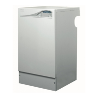
54
REASSEMBLY
1. Swing the control box down into the servicing
position. Refer to Frame 49.
2. Disconnect the condensate drain pipe.
3. Remove the screw and elongated bolt, pull
the trap down and forward to remove.
4. Flush out any deposits with clean water.
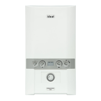
52
CLEANING THE CONDENSATE 'S' TRAP
1. Remove ignition and flame detection electrodes.
Refer to Frames 61 & 62.
2. Remove the 3 screws retaining the sump cover and
remove.
3. Using a suitable tool as supplied in the standard
British Gas Flue brush kit, clean between the heat
exchanger fins from the top of the heat exchanger.
4. Access to the base of the heat exchanger is now
possible. Brush clean any deposits from the base of
the heat exchanger and remove any loose deposits
from the sump.
5. Inspect the ignition and detection electrodes. Ensure
that they are clean and in good condition - replace if
necessary.
6. Check the condition of the combustion chamber
insulation. Any cracked or damaged pieces must be
replaced.
Note. Take care not to disturb the ionisation probes at the
front and rear of the combustion chamber.
7. Check that the ignition and detection gaps are
correct. Refer to Frames 61 & 62.
nm7401
2
Sump cover
3
Ionisation
probes
Heat exchanger
SERVICING
 Loading...