• Verify tester operation by measuring a
known voltage. Apply tester to circuit
under test. And, then test on the
known live voltage again to ensure
proper operation.
• Connect the black common lead to
ground before applying the red test lead
to voltage. Disconnect the red test lead
from the voltage first.
• Always work with a partner.
• When using the probes, keep fingers as
far behind the probe tips as possible.
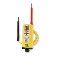
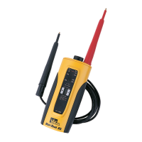
Features:
• Vibration Mode w/indicator movement
• Audible and LED Indication of Voltage
Levels (61-085 has LED indication only).
• Auto-Switching Voltage/Continuity
Technology (61-086 only)
• Independent solenoid and electronic cir-
cuitry design provides back-up voltage
indication for added safety.
• Low Impedance Measuring Device
• Replaceable Test Leads
• Shielded probe tips
• Ultrasonically welded and o-ring sealed
for added durability
Accessories:
• TL-82 Resistor-fused test leads
• C-90 Soft-sided carrying case
To Measure AC Voltage:
• Ensure that the plug for the test leads is
fully seated into the banana jacks.
• Connect the tester in parallel with the
load or circuit.
• The tester indicates both the voltage
type and the voltage level. (See Tester
Operation table)
To Measure DC Voltage:
• Ensure that the plug for the test leads is
fully seated into the banana jacks.
• Connect the tester in parallel with the
load or circuit.
• The tester indicates the voltage type,
polarity, and the voltage level. (See
Tester Operation table)
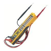
To Test for Continuity: (61-086 only)
• Ensure that the plug for the test leads is
fully seated into the banana jacks.
• De-Energize circuit before performing
continuity test. Note, if voltage is pres-
ent in the circuit, the tester automatical-
ly switches to voltage indication mode.
• Test for continuity by connecting the
tester to the circuit.
• If circuit has 500kΩ or less resistance,
an audible indication is heard and the
Continuity LED lights. (See Tester
Operation table)
• Reversing prods on the circuit under
test verifies continuity versus low volt-
age +DC.
 Loading...