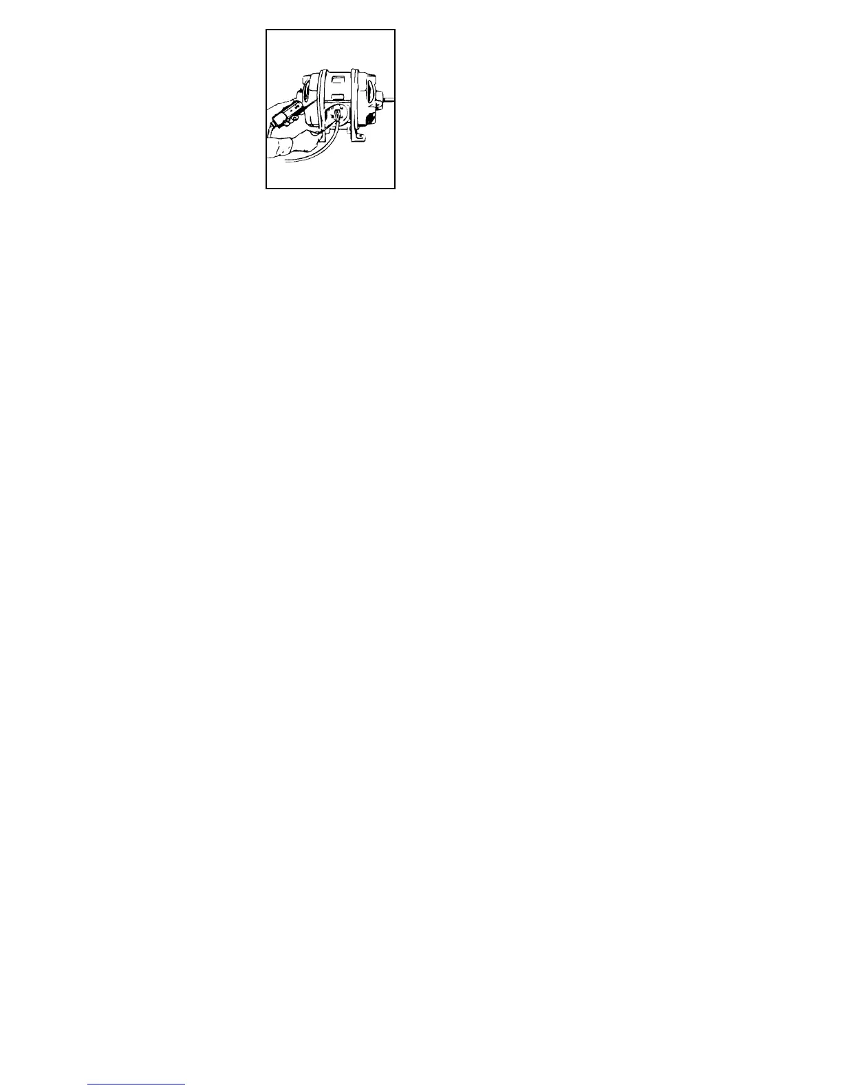
• Testing for
“Grounded” Side of
Motor or Appliance
With power to motor or
appliance “Off,” touch
one test prod to the
frame and the other
prod to each of the terminal connec-
tions. The terminal which turns the
continuity LED “On” is the grounded
side. With power to motor or appliance
“On,” place tester across the frame and
to each of the terminal connections.
The terminal which does not give a volt-
age indication, but does give a continu-
ity indication, is the grounded side.
• Testing for 25 to 60 Cycle
Frequency
Place tester between each side of AC
line. A low frequency hum and slow
vibrations indicate 25 cycle current. 60
cycle current is indicated by a higher
frequency hum and more rapid vibra-
tions.
• Checking Continuity of Cords,
Motors, Appliances, etc. (61-086
only)
Remove power source and place tester
across circuit to be tested. Continuity
LED turns “On” and an audible beep is
heard if resistance is less than 500K
ohms.
• Locating Excessive Leakage to
Ground
Place tester across the neutral terminal
and the ground, only the continuity light
should turn “On,” indicating neutral and
ground are connected. If the “ – DC”
light also turns “On,” there is 6VAC or
greater between neutral and ground
indicating a high resistance leakage to
ground. High resistance leakage is
qualified since a low resistance (high
current) leak to ground would open a
circuit breaker or blow a fuse.
Battery Replacement: (61-086 only)
• Replace batteries when touching the
leads together no longer lights the con-
tinuity LED or produces an audible
sound.
• Remove test leads from tester.
• Loosen the encapsulated screw from the
bottom of the case.
• Remove battery cap.
• Replace the batteries with (4) new 1.5V
button-type batteries (IDEAL# 61-201,
IEC #LR44, or NEOA# 1166A).
• Replace battery cap and re-tighten the
encapsulated screw.
Test Lead Replacement:
• Replace leads only with IDEAL test
leads below.
• # TL-80 Standard Test Leads with
Shielded Probe Tips
• # TL-82 Resistor-fused Test Leads
with Shielded Probe Tips. Each
probe tip contains a special, current-
limiting resistor which acts like a fuse
to limit short-circuit current and pre-
 Loading...