10
PS5R-V Switching Power Supplies
Mounting on DIN Rails
1. Use a 35mm-wide DIN rail.
2. Fasten the DIN rail to a mounting plate using screws.
3. Place the PS5R-V on the DIN rail as shown with input termi-
nal side up (
), and press the PS5R-V towards the DIN rail
(
). Make sure that the PS5R-V is installed rmly.
4. Use BNL6 mounting clips for fastening the PS5R-V on the
DIN rail. Use of BNL8 mounting clips is recommended when
excessive vibration or shock is anticipated. Do not use the
PS5R-V when it is subject to vibration constantly.
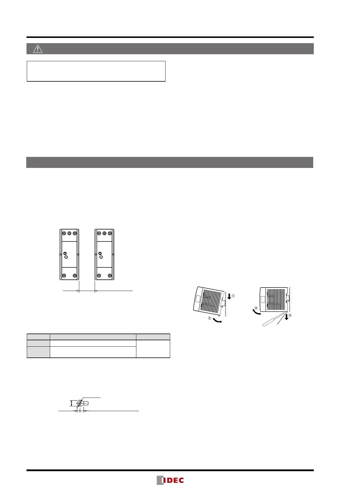
Removal
•Insert a at screwdriver into the slot in the clamp, and pull out
the clamp until it clicks (
). The lock mechanism is released
and the PS5R-V can be removed (
). When mounting the
PS5R-V again, push in the latch rst.
Notes for installation
•Do not close the top and bottom openings of the PS5R-V to
allow for heat radiation by convection.
•Maintain a minimum of 10 mm clearance around the PS5R-V,
except for the top and bottom openings.
•When mounting multiple PS5R-V switching power supplies
side by side, maintain a minimum of 10 mm clearance. Ob-
serve the derating curves in consideration of the ambient
temperature.
10mm minimum
•When the derating voltage may exceed the recommended
value, provide forced air-cooling.
•Make sure to wire the ground terminal correctly.
•For wiring, use wires of heat resistance of 60C or higher
(PS5R-VB: 80C or higher). Use copper wire of the following
sizes, according to the rated current.
Terminal Wire Size (allowable current) Wire Type
Input AWG18 to 14
Copper
Solid/Stranded
Output
AWG18 to 14
(AWG18: 7A, AWG16: 10A, AWG14: 15A)
Cross-sectional area
AWG18: 0.82mm
2
, AWG16: 1.31mm
2
, AWG14: 2.0mm
2
Note: Wires of the above size must be used to comply with
UL508, CSA C22.2 No. 107.1.
Applicable crimp terminal (reference)
4.1 max.
5.6 min. (PS5R-VG: 6.3 min)
•Recommended tightening torque of the input and output ter-
minals is 1.0 to 1.3 N·m (0.8 N·m for UL).
Safety Precautions
Operating Instructions
Mount the PS5R-V in an enclosure. Do not use the PS5R-V
alone as an Electric Facilities for General Use.
Use the PS5R-V for electric facilities for business use only.
•Do not use switching power supplies with electric equipment
whose malfunction or inadvertent operation may damage the hu-
man body or life directly.
•Make sure that the input voltage and output current do not ex-
ceed the ratings. If the input voltage and output current exceed
the ratings, electric shock, re, or malfunction may occur.
•Do not touch the terminals of the switching power supply while
input voltage is applied, otherwise electric shock may occur.
•Provide the nal product with protection against malfunction or
damage that may be caused by malfunction of the switching
power supply.
•Operating temperatures should not exceed the ratings. Be sure to
note the derating characteristics. If the operating temperature ex-
ceeds the ratings, electric shock, re, or malfunction may occur.
•Blown fuses indicate that the internal circuits are damaged. Con-
tact IDEC for repair. Do not just replace the fuse and reoperate,
otherwise electric shock, re, or malfunction may occur.
•Do not use the switching power supplies to charge rechargeable
batteries.
•Do not overload or short-circuit the switching power supply for
a long period of time, otherwise the internal elements may be
damaged.
•Do not disassemble, repair, or modify the power supplies, other-
wise the high voltage internal part may cause electric shock, re,
or malfunction.
•The fuse inside the PS5R-V switching power supply is for AC
input. Use a DC fuse for DC input.
 Loading...