11
PS5R-V Switching Power Supplies
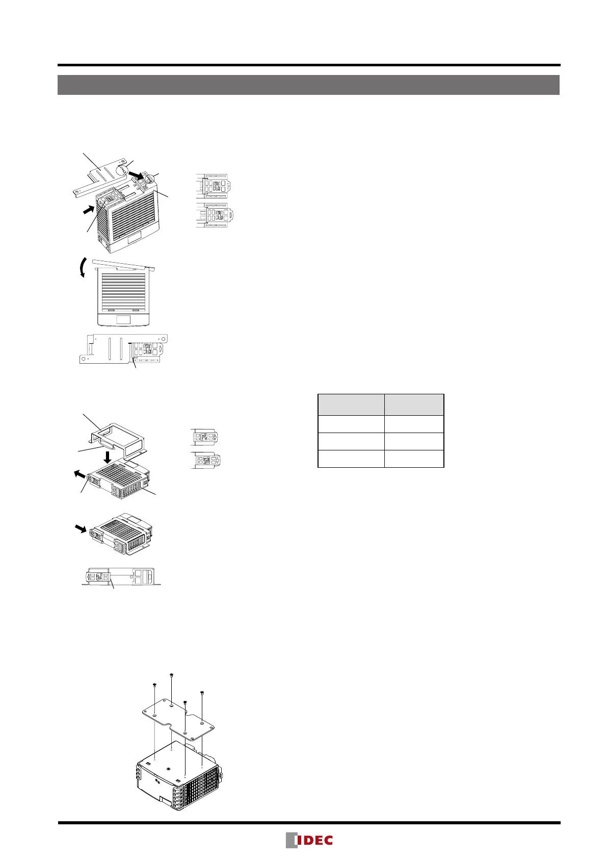
Installing the Panel Mounting Bracket
Latch
Latch
LOCK
LOCK
Panel Mounting Bracket (PS9Z-5R1)
Panel Mounting Bracket (PS9Z-5R2B)
Power
Supply
Power
Supply
Tab
Tab
Slot
<Installing PS9Z-5R1 Panel Mounting Bracket>
<Installing PS9Z-5R2B Panel Mounting Bracket>
LOCK
UNLOCK
LOCK
UNLOCK
Push in the latch to LOCK
position.
Install the tab on the panel
mounting bracket into the
slot on the power supply.
Install the brackets as
shown on the left.
Ensure that the panel
mounting bracket is locked
by the latch.
Pull out the latch to
UNLOCK position.
Insert the tab on the panel
mounting bracket into the
slot on the power supply.
Push in the latch to LOCK
position.
Ensure that the panel
mounting bracket is locked
by the latch.
Installing PS9Z-6R2F Side-mount Panel
Mounting Bracket
Install the bracket on the switching power supply using four
M3 × 6 countersunk screws supplied with the bracket.
Adjustment of Output Voltage
The output voltage can be adjusted within ±10% of the rated
output voltage (PS5R-VE: ±5%) by using the VR.ADJ control
on the front. Turning the VR.ADJ clockwise increases the out-
put voltage. Turning the VR.ADJ counterclockwise decreases
the output voltage.
Overcurrent Protection
The output voltage drops automatically when an overcurrent
ows due to an overload or short circuit. Normal voltage is
auto matically restored when the load returns to normal condi-
tions.
Insulation/Dielectric Test
When performing an insulation/dielectric test, short-circuit the
input (between L and N) and output (between +V and –V). Do
not apply or interrupt the voltage quickly, otherwise surge volt-
ages may be generated and the PS5R-V may be damaged.
Notes for Operation
•Output interruption may indicate blown fuses. Contact IDEC.
•The PS5R-V switching power supply contains an internal fuse
for AC input. When using with DC input, install an exter nal
fuse for DC input. To avoid blown fuses, select a fuse in con-
sideration of the rated current of the internal fuse.
Rated Current of Internal Fuses
Part No.
Internal Fuse
Rated Current
PS5R-VB/VC 2A
PS5R-VD/VE/VF 4A
PS5R-VG 6.3A
•Avoid overload and short-circuit for a long period of time,
oth erwise the internal elements may be damaged.
•DC input operation is not subject to safety standards.
Rust and Scratches on Metal parts
Hot-dip galvanized steel and bonderized steel are used for the
PS5R-V. Rust on the edge and scratches on the surfaces may
be developed depending on the storage condition, but the
performance of the PS5R-V is not affected.
Noise
Small acoustic noise inside the PS5R-V may be heard de-
pending on the input voltage and load, but the performance of
the PS5R-V is not affected.
Operating Instructions
 Loading...