12
STEEkW ed 12/03 EOLO Eco kW
13
STEEkW ed 12/03 EOLO Eco kW
Technical DocumentationTechnical Documentation
Technical Documentation
Technical Documentation
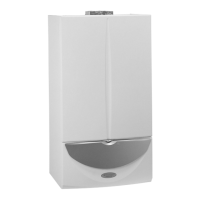
Flue circuit.
Operation.
e products of combustion, after having hit the water-gas
exchanger (2), are slowed down and distributed by the plate
(12) thus increasing combustion eciency. ey are then
conveyed to a draught diverter (4) on top of which the ue
extractor (fan) (5) is mounted.
Fan operation ensures forced expulsion of the ue and, at the
same time creates a vacuum in the sealed chamber (3) so the
combustion air can be extracted from outside.
Correct fume extraction is controlled by a dierential ue pres-
sure switch (6) that enables or prevents burner ignition.
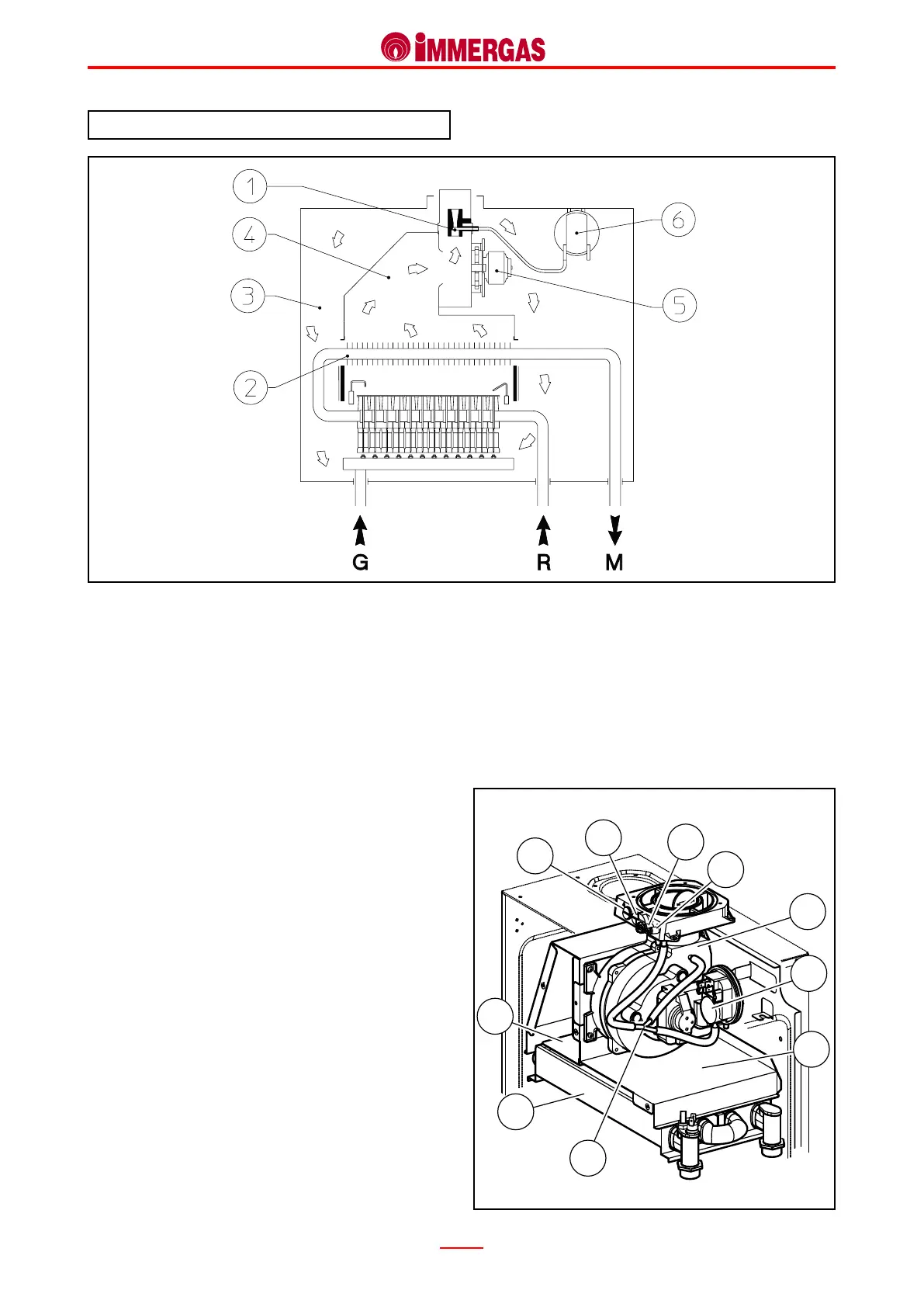
Air-ue intake traps (7-8).
e top outer part of the sealed chamber features two intake
traps with screw closing, accessible from the front and from
where combustion air (7) and ue (8) can be sampled.
Flue pressure switch signal pressure points (9-10).
e top outer part of the sealed chamber features two pressure
points with screw closing by means of which it is possible to
measure the signal on the ends of the ue pressure switch
(6).
e negative pressure point (9) is connected to a “Y” shaped
pipe (11) which, in turn, is connected to the negative pressure
point of the ue pressure switch (6) and to the pressure point
positioned at the outlet of the Venturi pipe inserted in the
fan’s exhaust terminal.
e positive pressure point (10) is connected directly to the
inside of the sealed chamber.
Flue pressure switch (6).
It is located at the top inside the sealed chamber and detects, by
means of the relative points, the dierence in pressure between
the outlet of the Venturi pipe inserted in the fan exhaust
(negative signal) and the inside of the sealed chamber
(positive signal).
e signal measured by the pressure switch is variable accord-
ing to the length of the air inlet/exhaust terminals and can be
 Loading...


