14
STEEkW ed 12/03 EOLO Eco kW
15
STEEkW ed 12/03 EOLO Eco kW
Technical DocumentationTechnical Documentation
Technical Documentation
Technical Documentation
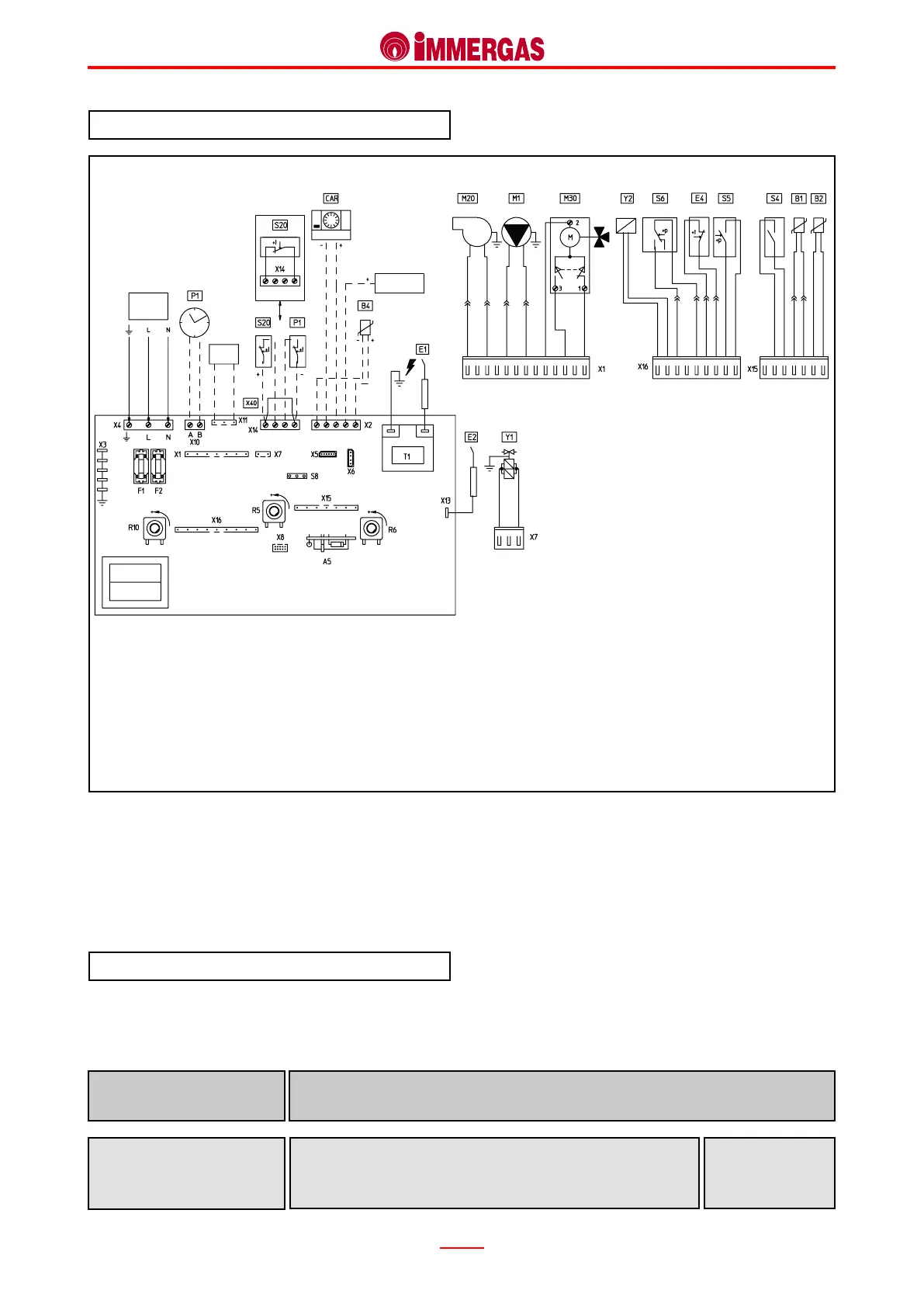
Electrical circuit.
The EOLO Eco kW electrical circuit is totally interlocked
to a microprocessor-controlled p.c.b. that controls generator
functions.
230 V AC circuit.
Safety devices and controls.
Some of the control and safety devices operate at mains
voltage (230 Vac) while the others at low voltage.
Legend:
A5 - CAR interface board
B1 - Delivery probe
B2 - D.h.w. probe
B4 - External probe (optional)
CAR- Remote control (optional)
CZ - Zone control unit (optional)
E1 - Ignition electrode
is detects ignition of the burner by whose ame it is covered.
It is connected to the integrated board.
Detection electrode
(E2)
ey interrupt power to the circuit when power input is over
3.15 A.
ey are tted on the integrated board.
Line fuse (F1)
Neutral fuse (F2)
Fuse
3,15 AF 250 V
E2 - Detection electrode
E4 - Overheating safety thermostat
F1 - Line fuse
F2 - Neutral fuse
M1 - Circulator
M20- Fan
M30- Moterized 3-way diverter valve
P1 - Central heating timer (optional)
R5 - D.h.w. temperature trimmer
R6 - Central heating temperature trimmer
R10 - Main selector switch
S4 - D.h.w. ow switch
S5 - System pressure switch
S6 - Flue pressure switch
S8 - Gas type selector switch
S20 - Room thermostat (optional)
T1 - Ignition transformer
X40 - Room thermostat jumper
Y1 - Gas valve
Y2 - Gas valve modulation coil
 Loading...