4
STEEkW ed 12/03 EOLO Eco kW
5
STEEkW ed 12/03 EOLO Eco kW
Technical DocumentationTechnical Documentation
Technical Documentation
Technical Documentation
Primary circuit (boiler circuit).
e primary circuit with relevant control and safety devices
is triggered each time there is a request for central heating
or domestic hot water.
Operation.
e heat contained in the ue produced by combustion is ab-
sorbed by the copper blades of the primary water-gas exchanger
(7) which, in turn, transfers it to the water circulating inside
it by means of the boiler pump (15).
e water is transferred directly into the system or else can
be diverted inside the stainless steel instantaneous plate ex-
changer (3).
is depends on the position of the motorised 3-way valve
(16) which, when idle, lets the water ow through the d.h.w.
exchanger (3); on the other hand, when responding to a heating
request, the ow is diverted to the system delivery (M) and
return (R) pipes.
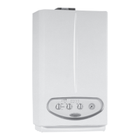
Flow-head graph.
e trend of the curve that represents the system’s ow-head
ratio depends on how fast the pump is working and on how
the system by-pass is adjusted. Depending on the position,
it provides the system with a higher or a smaller head. e
characteristic curves are shown in the following graphs.
Head (kPa)
Flow rate Litres/h
A
A = Head available to the system on maximum speed with the by-pass o
(adjustment screw fully tightened)
B = Head available to the system on maximum speed (screw tightened
1.5 turns compared to the adjustment screw completely loose)
C = Head available to the system on maximum speed with the by-pass
open (adjustment screw completely loose)
Head (m H
2
O)
Boiler circulator (1).
It works on the primary circuit return, located immediately
after the 3-way diverter valve to which it is connected.
It is part of the integrated multi-function unit made in a
compound material.
A space on the body houses the automatic air vent (2).
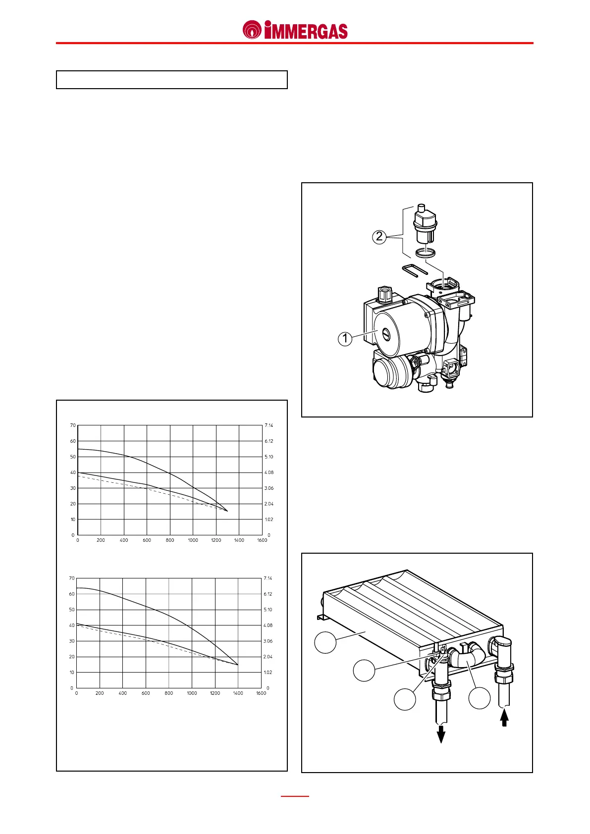
Primary exchanger (1).
It is a water-gas lamellar exchanger with copper pipes and ns
(N° 75 ns 24 kW version) (N° 98 ns 28 kW version). e
central heating delivery NTC probe (2) and the overheating
safety thermostat (3) are located on the exchanger’s outlet
(delivery).
e four pipes it is made of are connected in series (4).
It is connected to the pump delivery and primary circuit deli-
very by means of pipes with threaded ttings.
Delivery
Return
EOLO Eco 24 kW
Head (kPa)
Flow rate Litres/h
Head (m H
2
O)
EOLO Eco 28 kW
B
C
A
B
C

 Loading...