2
STEEkW ed 12/03 EOLO Eco kW
3
STEEkW ed 12/03 EOLO Eco kW
Technical DocumentationTechnical Documentation
Technical Documentation
Technical Documentation
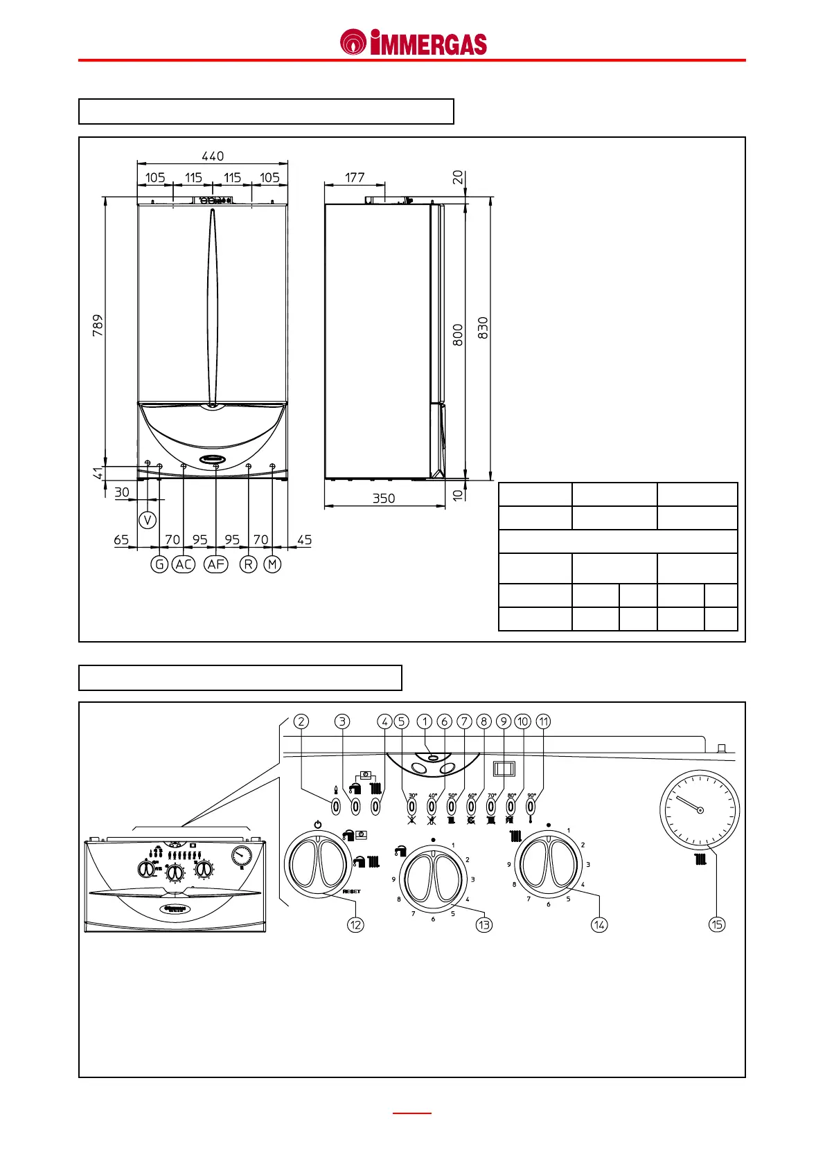
EOLO Eco kW Main dimensions and connections.
Legend:
G - Gas supply
AC - D.h.w. outlet
AF - D.h.w. (cold) inlet
R - System return
M - System delivery
V - Electrical connection
EOLO Eco kW Control panel.
Legend:
1 - Stand by LED
2 - Burner on LED
3 - D.h.w. on LED
4 - Central heating on LED
5 - Temperature LED – Ignition stop malfunction
6 - Temperature LED – Flue pressure switch malfunction
7 - Temperature LED – System pressure insucient malfunction
8 - Temperature LED – Circulation insucient malfunction
9 - Temperature LED – Delivery probe faulty
10 - Temperature LED – Domestic hot water probe faulty
11 - Temperature LED – Overheating lock
12 - Stand-by-D.h.w./Remote Control (CAR)-D.h.w. and Heating-Reset-
selector switch
13 - D.h.w. temperature knob
14 - Central heating temperature knob
15 - Boiler manometer
Height (mm) Width (mm) Depth (mm)
830 440 350
CONNECTIONS
GAS
DOMESTIC
HOT WATER
SYSTEM
G AC AF R M
1/2” 1/2” 1/2” 3/4” 3/4”
 Loading...


