Application Note 18 2011-07-06
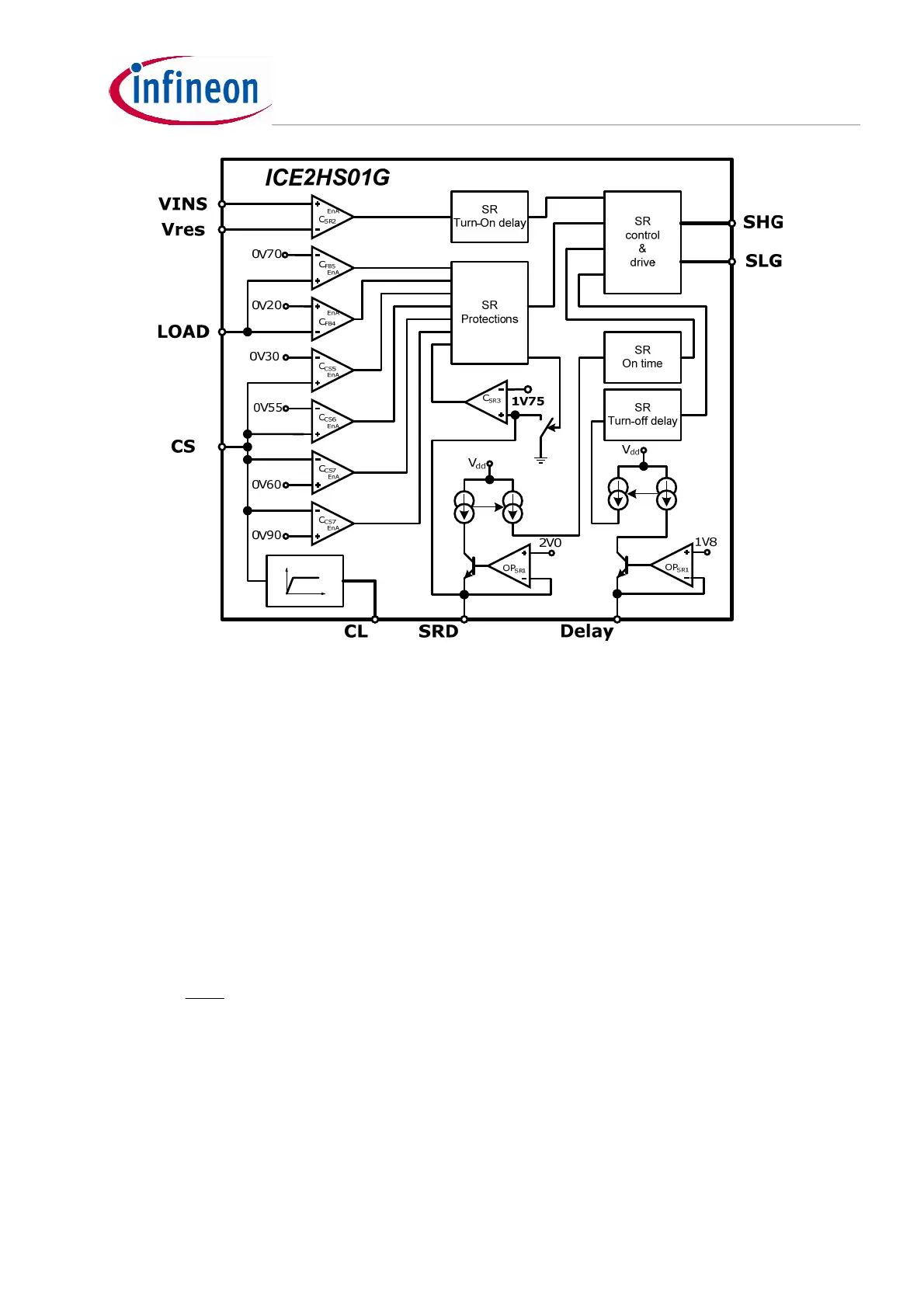
Figure 8 Synchronous rectification control block diagram
2.4.1 On-time control - SRD pin and CL pin
With ICE2HS01’s control scheme, SR MOSFET ‘s turning-off depends on two conditions - turning-off of
the primary gate and the “off” instruction from SR on-time block, where the maximum on-time
max_on
T is
preset. Whichever “off” instruction comes first will trigger the turn-off of the SR MOSFET.
As illustrated in the previous chapter, the
max_on
T depends on the resonant frequency when LLC
converter operates below resonant frequency (
sw
f <
r
f ). Considering the primary side dead time
DEAD
T
and the SR gate turn-on delay
delayon
T
_
( will be discussed later section 2.4.2), we can preset
max_on
T with
a safe value as below:
usTT
f
T
delayonDEAD
res
on
31.525.032.088.5
2
1
_max_
=−−=−−< [27]
To achieve higher efficiency, a bigger
max_on
T is an advantage, because bigger on-time means longer SR
MOSFET conduction time and less body diode conduction time, which reduces conduction loss. In actual
design,
max_on
T can be fine-tuned by looking at the similar waveforms in Figure 7, as long as safe
switching is guaranteed.
 Loading...
