Application Note 24 2011-07-06
3 Tips on PCB layout
In order to avoid crosstalk on the board between power and signal path, and to keep the IC GND pin as
“clean” from noise as possible, the PCB layout must be taken care of properly. Below are some
suggestions as reference and customer can modify based on their own experience.
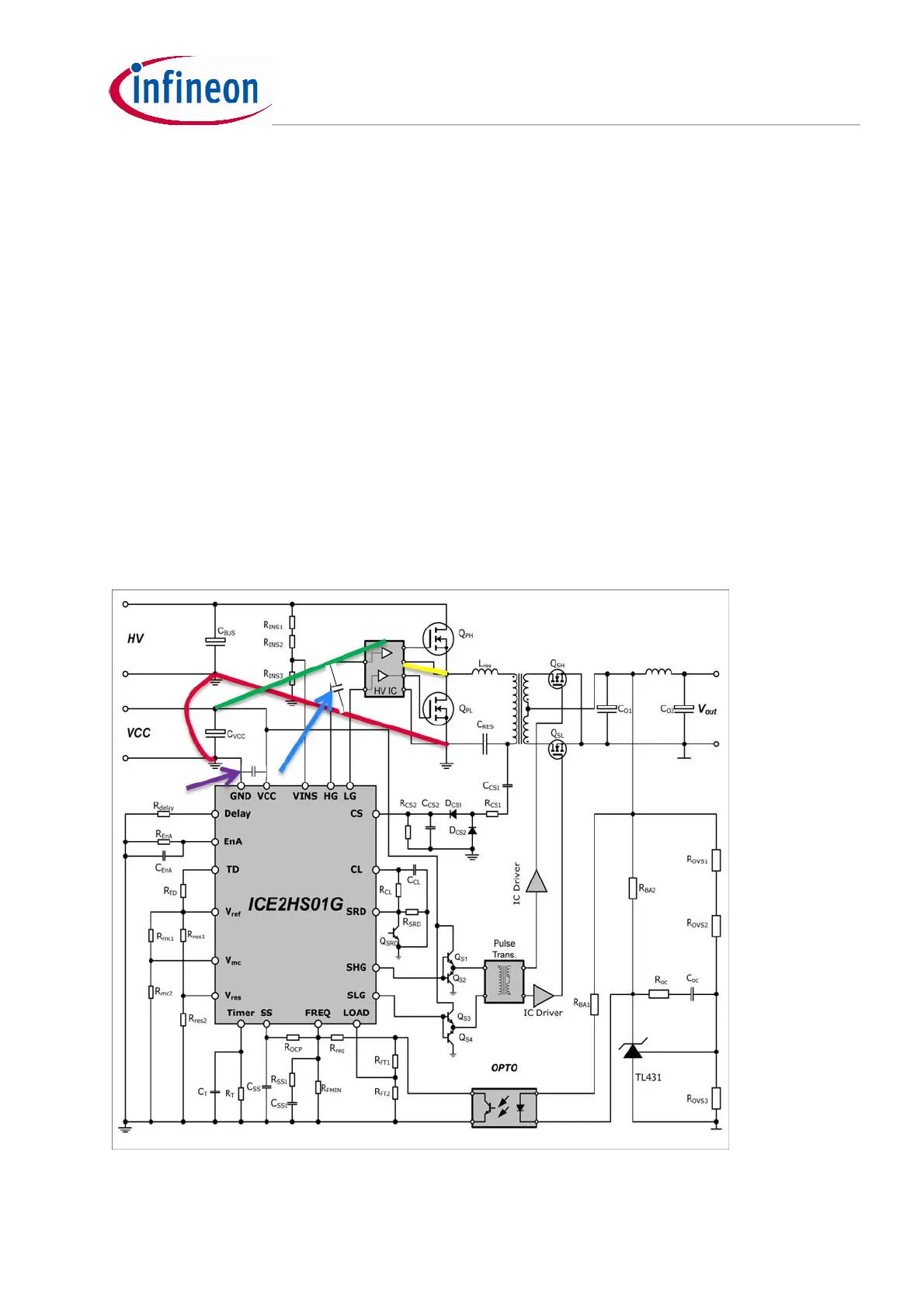
3.1 Star connection for Power stage
1. Connect IC VCC Ecap ground to both buck cap. ground and IC VCC ground (please refer to
the red curves in the circuit diagram below)
2. Connect driver IC input ground to IC VCC Ecap ground
3. Connect driver IC output ground to low side MOS source with short path
4. A 100nF filtering cap should be located just near IC VCC & IC GND (refer to the purple arrow)
5. The 100nF filtering cap ground should be inserted between VCC Ecap ground and IC ground
6. Connect driver IC VCC to VCC Ecap(refer to the green curve)
7. Connect driver IC high side output source to half bridge midpoint directly with short path
8. A 100nF filtering cap should be located just near driver IC VCC and IC GND(refer to the blue
arrow)
Figure 15 PCB layout tips
shorted
 Loading...
