1 Hardware
The Evaluation Kit is available in two versions. Version S includes an Eval PCB with an Arduino form-factor. It
supports a quick and easy plug & play evaluation of the Next Gen Solenoid Driver. Version L includes the Eval
PCB and an additional Connection PCB. The Version L is the more advanced setup option for detailed
laboratory measurements.
1.1 Eval PCB
The Version S includes the Evaluation PCB with the Next Gen Solenoid Driver TLE92464ED and all required
external components on it. The Evaluation PCB is desgined on an Arduino Formfactor which makes it
controlled by all Arduino compatible microcontroller boards, e.g.:
Infineon XMC1100 Boot Kit
Infineon XMC4700 Relax Kit
Aurix ShieldBuddy TC275
Arduino Uno
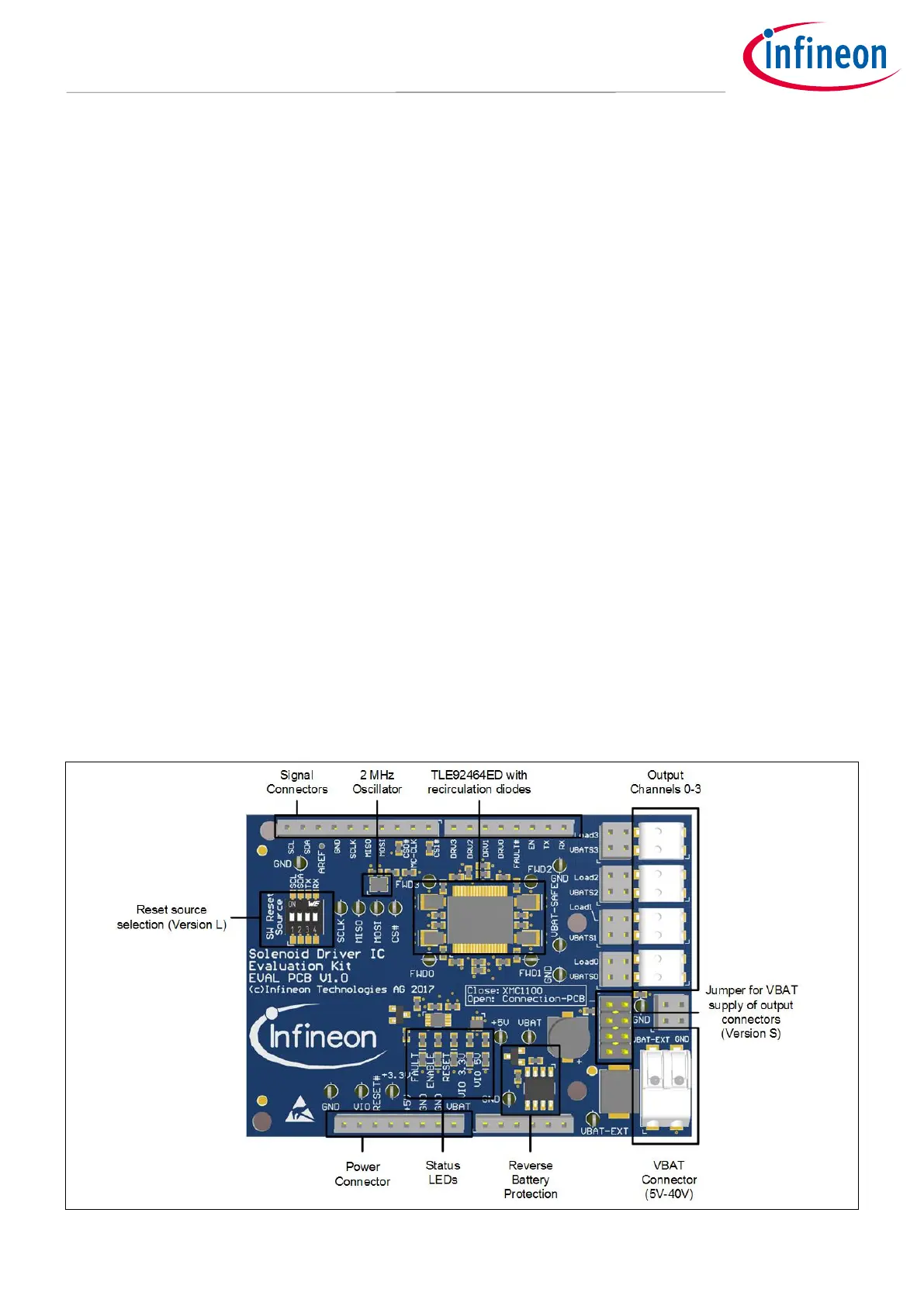
Figure 1/Figure 2 give an overview of the component blocks on the Evaluation PCB for
TLE92464ED/TLE92466ED. The IC itself is powered with 5V via the microcontroller board (version S) or the
Connection PCB (version L), respectively. The load supply voltage VBAT which is available at the output channel
connectors can be applied via the VBAT connector in version S (close JP1 – Pin Header, refer Jumper Options).
In version L the VBAT level is supplied via the Connection PCB. The IC is clocked by an external rectangular 2
MHz oscillator. Another external clock source (e.g. microcontroller) can be selected via the ohmic Jumper
(R12/R13). The SPI signals, the ENABLE signal and the RESETN signal must be provided by the microcontroller
to enable a successful communication between the microcontroller and the TLE92464ED. The FAULTN and the
DRVx signal are only necessary if the according features are used. The status LEDs indicate wheter the
corresponding function is active (glowing) or not. The reset source DIP switch enables the selection of different
pins for the RESETN signal. This option is only needed for the operation with multiply Evaluation PCBs.
 Loading...


