User Manual 7 V1.1
2021-05-03
Next Generation Solenoid Driver
Evaluation Kit User Manual
Evaluation PCB Signal Name
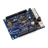
1.1.2 Jumper Options
On the Evaluation PCB are various configuration options available to enable all features in both versions (S and
L) and to test the chip in different conditions. The jumper options are descriped in the table below.
Table 5 Jumper Options
External 2MHz Oscillator source
Microcontroller Clock source via Connector
Pin MC-CLK (e.g. PWM signal)
Chip select signal source
SPI chip select via Connector Pin CS0#
SPI chip select via Connector Pin CS1#
DIP Switches open (default)
RESET# Pin as Reset signal source
SCL Pin as Reset signal source
SDA Pin as Reset signal source
TX Pin as Reset signal source
RX Pin as Reset signal source
Pin header JP1 closed (default)
Supply Output Connector with VBAT voltage
level via VBAT-EXT Connector
Evaluation PCB Output Connectors are
supplied via the Connection PCB
Note: Open for use with Connection PCB
1.1.3 LEDs
The Eval PCB has five LEDs which indicate the status and operating conditions of the IC. The meaning of the
status LEDs is descriped below.
Table 6 LED description
TLE92464ED Pin designation
Glows if the IC detected a fault condition
Glows if the IC is enabled
Glows if the IC is in reset state
Glows if the VIO Pin is connected to 3.3V
(voltage level for SPI MISO Pin)
Glows if the VIO Pin is connected to 5V
(voltage level for SPI MISO Pin)
1.2 Connection PCB
The version L includes the Evaluation PCB, the Connection PCB and an Infineon Aurix TriBoard TC277. The
Connection PCB supports the evaluation of up to three Evaluation PCBs in parallel. Furthermore it provides
advanced measurement options and one high side switch for each Evaluation PCB. The control unit for version

 Loading...