User Manual 4 V1.1
2021-05-03
Next Generation Solenoid Driver
Evaluation Kit User Manual
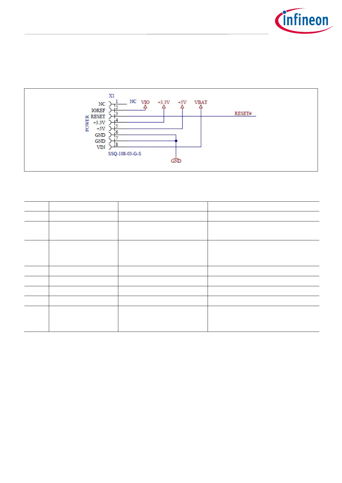
1.1.1 Connector Interface for Arduino
The Connector placement of the Evaluation PCB is compliant with the Arduino form-factor. The pinouts are
listed below.
Figure 3 Power Connector X1
Table 1 Power Connector X1
Evaluation PCB Signal Name
Voltage level for the SPI-MISO-Signal
(3V3 or 5V)
Reset signal (low active) for the
TLE92464ED. All Reset signal source
DIP-switches should be open.
Voltage Level (usually 12V) applied on
the VBAT-Connector to supply the
Arduino board
 Loading...


