30
measurements return to normal, repeat procedure and use process of elimination
to find cause.
1.5 External 5 VDC Short Circuit:
Background
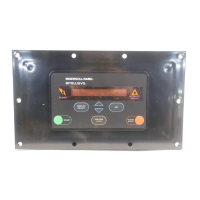
The Intellisys provides two 5 VDC signals for external use. The logic supply
voltage is used by the Intellisys to supply power for internal circuitry such as the
EPROM, RAM, Microprocessor, etc. The logic supply is also used to supply
power to an external device known as the “Option Module”. This connection is
made via connector J11. J11 is a 5-pin connector located on the left side of the
controller (viewed from the front). The “Option Module” should always be
installed or removed with power off. Note: the “Option Module” can be potentially
damaged if installed with power on. Installing the module with power on can
cause a latch-up condition which can create an excessive amount of current
draw. This condition can cause the 5 VDC logic supply to sag below 4.5 VDC,
which will create abnormal controller behavior.
An intermittent connection to the “Option Module” can cause the same latch-up
condition as installing it with power on. Intermittent connections can be caused
by improper installation, bent connection pins, moisture contamination, corrosion
of electrical contacts, or excessive vibration.
Procedure
This voltage measurement can be made with a Fluke 87 meter (or equivalent). A
recording meter (Fluke 87) is preferred for intermittent problems. Remove power
from machine. Remove back cover of Intellisys and locate J11 connector.
Insure static precautions are used when handling circuit board. Re-apply power
to machine. Set meter for Volts DC and connect and take measurements as
noted:
Connect from J11-1 to J11-5 (Top and bottom pin)
Expected value = 5 VDC +/- .2 VDC
A second 5 VDC signal from the Intellisys is supplied to provide power for the
sensors. This signal is externally supplied through J2 and J3 connectors. This
signal is provided for both pressure transducers and thermistors (temperature). If
this signal is short circuited externally, abnormal controller behavior will occur.
This could cause sensor reading errors, invalid calibration, sensor faults, sensor
warnings, or general shutdown “Ready to Start”. Potential root causes include
wiring fault to ground (chassis, sensor ground, or shield wire), moisture/corrosion
contamination of connector or sensor, and solenoid fault to pressure transducer
chassis.

 Loading...


