38
Procedure
With a known good incandescent light connected to the output terminal, a digital
voltmeter can easily read whether or not the triac is on or off. 115 VAC means
on, a 0 VAC means off. This is the best way to monitor outputs on any Intellisys
Controller.
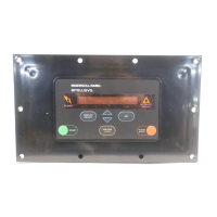
For the original Intellisys Controller there is an additional problem to determine
whether the faulty part is the controller or the Starter Interface Board.
Refer to Section B, Page 28, in the blue Field Service Manual for assistance
in determining the faulty part.
2.6 AUXILIARY CONTACTS
BACKGROUND
Auxiliary contacts are small contacts that are mounted on the front or sides of
starters. These contacts operate at the same time as the starter. The contacts
can be either normally open or normally closed. Some of the contacts are used
in both the 120 VAC control circuit and the low voltage control circuit for feedback
to the Intellisys controller. The procedure below covers how and where to test
the auxiliary contacts that are in the low voltage circuits.
PROCEDURE
Original Intellisys Controller
Contact 1Ma (mounted on the 1M starter contactor.)
Connect voltmeter set to volts DC to terminals BTS2-15 & 14 on the starter
interface board. You should read 5 VDC when 1M is de-energized and 0 VDC
when 1M is energized.
Star Delta Starting Only
Contact 1Sa (mounted on the 1S starter contactor).
Connect voltmeter set to volts DC to terminals BTS2-13 & 12 on the starter
interface board. You should read 5 VDC when 1S is de-energized and 0 VDC
when 1S is energized.
Star Delta Starting Only
Contact 2Ma (mounted on the 2M starter contactor).
Connect voltmeter set to volts DC to terminals BTS2-13 & 12 on the starter
interface board. You should read 5 VDC when 2M is de-energized and 0 VDC
when 2M starter is energized.
SE Intellisys Controller
Contact 1Ma (mounted on the 1M starter contactor).

 Loading...


