GENERAL INFORMATION
11
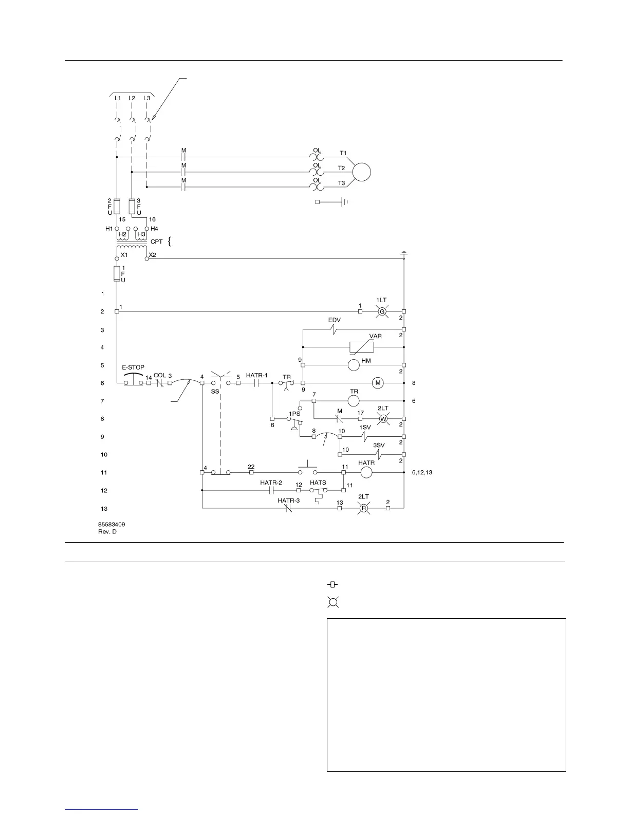
SEE TRANSFORMER NAMEPLATE FOR
WIRING CONNECTION REQUIREMENTS.
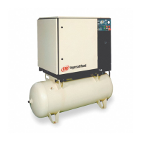
COMPRESSOR
MOTOR
“POWER ON”
OFF ON
“STAND BY”
“HI TEMP SHUTDOWN”
RESET
SEE NOTES 1 & 2
LINE
NUMBER
TO SUPPLY
JUMPER
JUMPER
LEGEND
CPT
Transformer, control
EDV
Valve, electric drain
E–STOP
Button, emergency stop
FU
Fuse
HM
Hourmeter
HATR
Relay, high air temperature
HATS
Switch, high air temperature
M Contactor (main)
OL
Overload, motor starter
PS
Switch, pressure
SS Switch, selector
1SV Valve, solenoid (Load) N.C.
3SV Valve, solenoid (Blowdown) N.O.
TR
Relay, time delay (6 min)
VAR V
aristor
Terminal points
L1, L2, L3 Light, transformer type
NOTES
1. Approved fused disconnect or circuit breaker per code
requirements must be provided by customer.
2. Dashed lines represent wiring by customer.
3. Sizing of electrical components not supplied by Ingersoll Rand is
the responsibility of the customer and should be done in
accordance with the information on the compressor data plate
and local electrical codes.
4. Unit will not restart automatically after power outage.
5. Circuit shown in normal position de–energized.
6. All wiring to be in accordance with local codes.
 Loading...