EasyManuals Logo

Ingersoll-Rand UP6 15 User Manual

Ingersoll-Rand UP6 15
143 pages
To Next Page IconTo Next Page
To Previous Page IconTo Previous Page
Page #14 background imageLoading...
Page #14 background image
INSTALLATION / HANDLING
12
ROTATION
VIEW LEFT
VIEW FRONT
VIEW RIGHT
VIEW TOP
VIEW BOTTOM
VIEW REAR
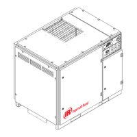
BASE MOUNTED UNITS
KEY
A Pre filter
B Compressor and cooling air intake
C Starter box
D Cooling air exhaust
E 1.00” NPT air discharge
F Customer power inlet
G Fork lift openings
(Fork lift hole covers must be installed after unit is in place to
reduce noise and ensure proper cooling of package)
H 4 slots 15 (0.6) x 25 (1.0)
See notes – Page 15
5
6

Questions and Answers:

Question and Answer IconNeed help?

Do you have a question about the Ingersoll-Rand UP6 15 and is the answer not in the manual?

Ingersoll-Rand UP6 15 Specifications

General IconGeneral
BrandIngersoll-Rand
ModelUP6 15
CategoryAir Compressor
LanguageEnglish

Related product manuals