Installation 7
Installation and Programming manual
2-3Wiring the device
The following paragraphs describe the various ways of connecting
the Ivy unit to an intrusion control panel. All connections involve the
terminals on the motherboard (Table 4, F). Each terminal can be
configured separately during the programming phase.
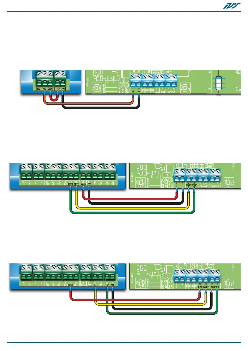
2 WIRE
CONNECTION
This standard wiring method activates the alarm signal by means of
a positive-power-removed signal.
4 WIRE
CONNECTION
This wiring method activates signaling via the START terminal and
deactivates it via the STOP terminal. The polarity of both inputs is
programmable.
The sounder/flasher is activated by an open-collector output (on the
intrusion control panel). By means of a second open-collector
output, you can deactivate alarm signals and disable (block) the
sounder/flasher from the intrusion control panel, for example,
during maintenance sessions.
EXTRA
CONNECTIONS
Connection of the LED terminal to an open-collector output allows
management of the STATUS and PRG LEDs, flasher and horn directly
from the intrusion-control panel (as programmed).
Connection of the FAULT and TAMPER outputs to a terminal on the
intrusion control panel allows signaling of the associated events.
This function allows fault and tamper signals to be transmitted
without activating the visual-signaling components.

 Loading...