Intel NUC Board D54250WYB and Intel NUC Board D34010WYB
Technical Product Specification
46
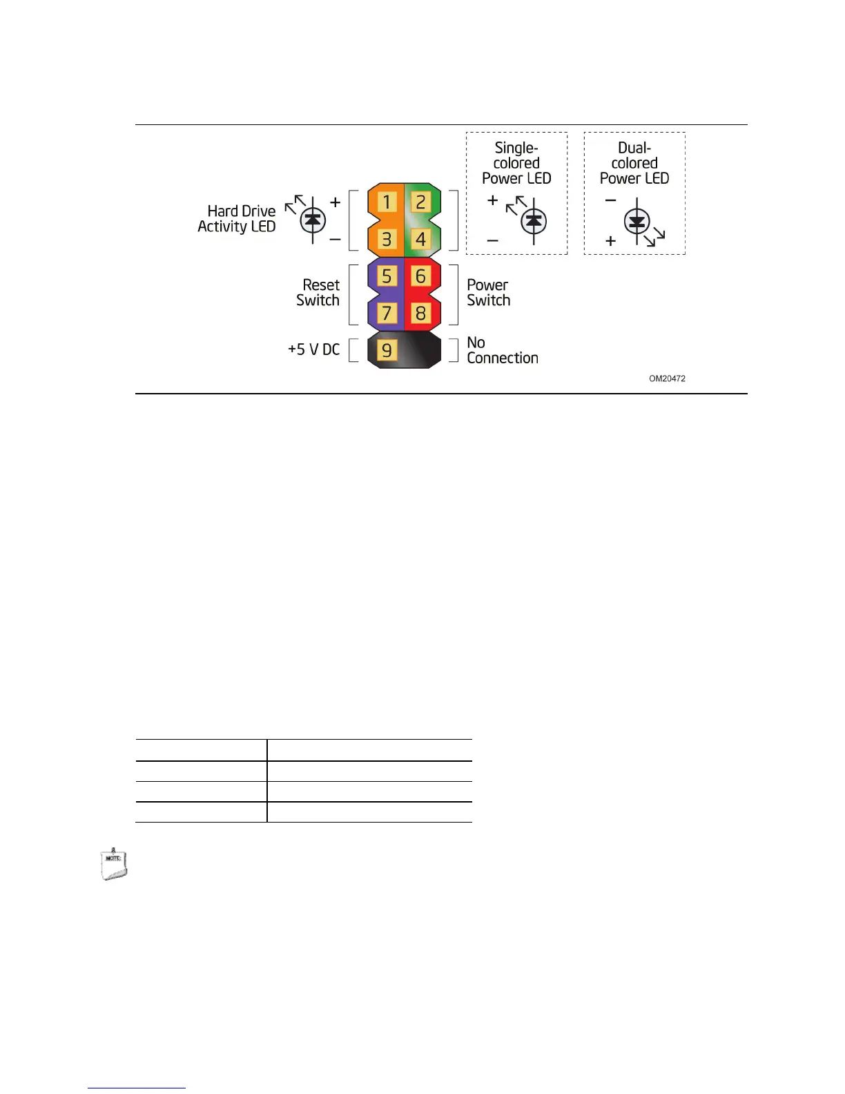
Figure 13. Connection Diagram for Front Panel Header (2.0 mm Pitch)
2.2.4.4.1 Hard Drive Activity LED Header
Pins 1 and 3 can be connected to an LED to provide a visual indicator that data is
being read from or written to a hard drive. Proper LED function requires a SATA hard
drive or optical drive connected to an onboard SATA connector.
2.2.4.4.2 Reset Switch Header
Pins 5 and 7 can be connected to a momentary single pole, single throw (SPST) type
switch that is normally open. When the switch is closed, the board resets and runs the
POST.
2.2.4.4.3 Power/Sleep LED Header
Pins 2 and 4 can be connected to a one- or two-color LED. Table 21 shows the
possible LED states.
Table 21. States for a One-Color Power LED
LED State Description
Off Power off
Blinking Standby
Steady Normal operation
NOTE
The LED behavior shown in Table 21 is default – other patterns may be set via BIOS
setup.
 Loading...