EasyManuals Logo

Intel DQ57TM User Manual

Intel DQ57TM
97 pages
To Next Page IconTo Next Page
To Previous Page IconTo Previous Page
Page #54 background imageLoading...
Page #54 background image
Intel Desktop Board DQ57TML Technical Product Specification
54
2.2.2.4 Front Panel Header
This section describes the functions of the front panel header. Table 28 lists the signal
names of the front panel header. Figure 12 is a connection diagram for the front panel
header.
Table 28. Front Panel Header
Pin
Signal
In/
Out
Description
Pin
Signal
In/
Out
Description
Hard Drive Activity LED Power LED
1 HD_PWR Out Hard disk LED
pull-up to +5 V
2 FP_LED+ Out Front panel green
LED
3 HDA# Out Hard disk active
LED
4 FP_LED Out Front panel yellow
LED
Reset Switch On/Off Switch
5 Ground Ground 6 PWR# In Power switch
7 FP_RESET# In Reset switch 8 Ground Ground
Power Not Connected
9 +5 V Power 10 N/C Not connected
Figure 12. Connection Diagram for Front Panel Header

Table of Contents

Other manuals for Intel DQ57TM

Questions and Answers:

Question and Answer IconNeed help?

Do you have a question about the Intel DQ57TM and is the answer not in the manual?
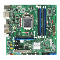
Intel DQ57TM Specifications

General IconGeneral
Form FactorMicro ATX
ChipsetIntel Q57
SocketLGA 1156
Memory TypeDDR3
Memory Slots4
Maximum Memory16 GB
PCI Express x16 Slots1
PCI Express x1 Slots2
PCI Slots1
SATA Ports6
eSATA1
USB Ports12
EthernetGigabit Ethernet
RAID SupportRAID 0, 1, 5, 10
Video OutputDVI, VGA
AudioRealtek ALC888S

Related product manuals