Intel
®
Server Board S5500BC User’s Guide xiii
List of Figures
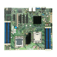
Figure 1. Intel
®
Server Board S5500BC.....................................................................................1
Figure 2. Server Board Connector and Component Locations ..................................................3
Figure 3. Configuration Jumper Locations .................................................................................5
Figure 4. Back Panel Connectors...............................................................................................7
Figure 5. DIMM Configuration Diagram....................................................................................10
Figure 6. Channel Slots Configuration .....................................................................................11
Figure 7. Installing Memory......................................................................................................14
Figure 8. Lifting the Load Lever................................................................................................15
Figure 9. Open the Load Plate .................................................................................................16
Figure 10. Remove the Socket Protective Cover .....................................................................16
Figure 11. Remove the Processor Protective Cover ................................................................16
Figure 12. Installing the Processor...........................................................................................17
Figure 13. Close the Load Plate and Socket Lever..................................................................17
Figure 14. 2U Reference Heat Sink Assembly.........................................................................18
Figure 15. Removing the PCI Riser Assembly from the Server System ..................................20
Figure 16. Installing a PCI Card in a Riser Card ......................................................................21
Figure 17. Replacing the Backup Battery.................................................................................23
Figure 18. BIOS Recovery Jumper ..........................................................................................29
Figure 19. Password Recovery Jumper ...................................................................................30
Figure 20. CMOS Recovery Jumper ........................................................................................31
Figure 21. Diagnostic LED Placement Diagram.......................................................................51
 Loading...


