Intel
®
E7500 and Intel
®
E7501 Chipsets MCH Thermal Design Guide
20 Thermal Design Guide
6.3.1 Retention Method A
Retention Method A employs the use of a clip and two solder-down through board anchors for
mechanical retention. This method is preferred when layout constraints hamper the use of
Retention Method B.
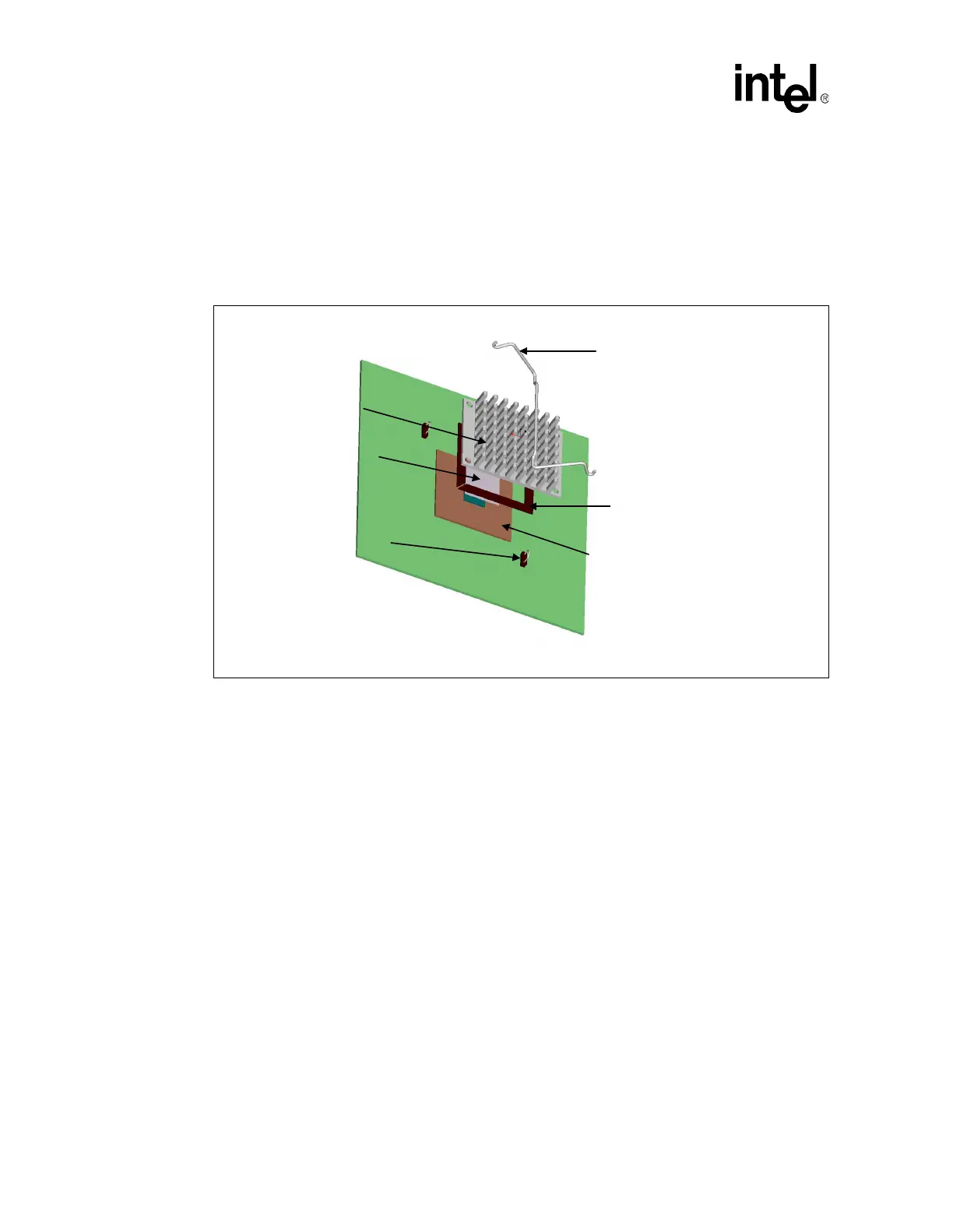
Figure 9 shows the reference thermal solution assembly using Retention Method A.
6.3.1.1 Heat Sink Orientations
When using Retention Method A, the heat sink must be aligned as shown in Figure 9. The heat sink
holes on the same side of the heat sink must be parallel with the clip that applies pressure through
the center of the heat sink.
The airflow may approach the heat sink from either perpendicular direction. Aligning the heat sink
45° relative to the airflow is acceptable but delivers reduced thermal performance.
6.3.1.2 Board Level Keep-out Dimensions
The locations of hole patterns and keep-out zones for the reference thermal solution are shown in
Figure 10 and Figure 11.
Figure 9. Reference Thermal Solution Assembly Using Retention Method A
Heat Sink
Thermal Interface
Solder-Down Anchor
Clip
Mechanical Interface
FC-BGA Package
 Loading...