Intel
®
E7500 and Intel
®
E7501 Chipsets MCH Thermal Design Guide
22 Thermal Design Guide
6.3.1.3 Heat Sink Clip
Retention Method A employs the use of a wire clip with hooked ends. The hooks attach to anchors
to fasten the clip to the board. See Figure 16 in Appendix B, “Mechanical Drawings” for a
mechanical drawing of the clip.
6.3.1.4 Solder-Down Anchors
For platforms that have very limited board space, a clip retention solder-down anchor has been
developed to minimize the impact of clip retention on the board. It is based on a standard three-pin
jumper and is soldered to the board like any common through-hole header. A new anchor design is
available with 45° bent leads to increase the anchor attach reliability over time. See Appendix A,
“Thermal Solution Component Suppliers” for the part number and supplier information.
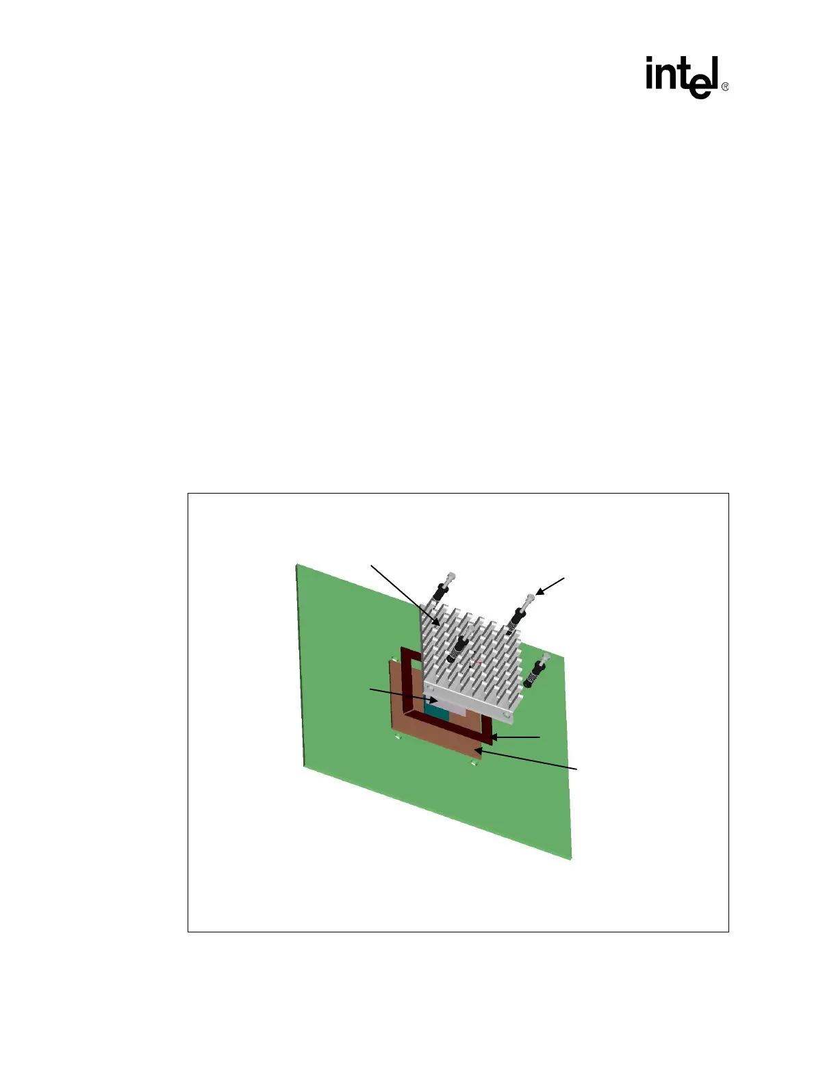
6.3.2 Retention Method B
Retention Method B employs the use of four push-pins mounted through the four holes on the heat
sink and the motherboard. This method requires advance layout notification for the four through
holes on the motherboard.
Figure 12 shows the reference thermal solution assembly using Retention Method B.
Figure 12. Reference Thermal Solution Assembly Using Retention Method B
Heat Sink
Thermal Interface Material
Push-pin
Mechanical Interface
FC-BGA Package
 Loading...