Intel
®
E7500 and Intel
®
E7501 Chipsets MCH Thermal Design Guide
Thermal Design Guide 21
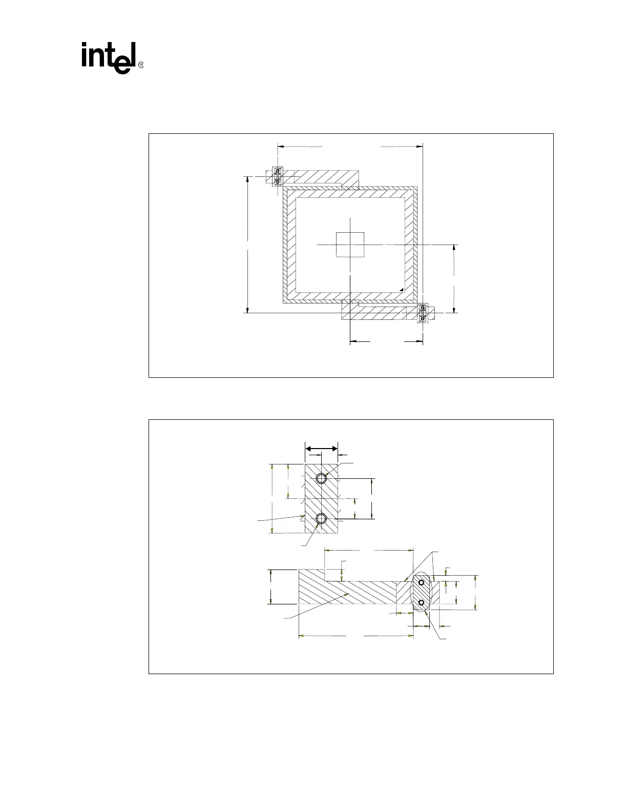
Figure 10 shows the heat sink retention mechanism layout for Retention Method A.
Figure 11 shows the retention mechanism component keep-out zones for Retention Method A.
Figure 10. Heat Sink Retention Mechanism Layout for Retention Method A
NOTE: Drawing dimensions are in millimeters [in] and are not to scale.
2X 30.45 [1.199]
2X 28.17
[1.109]
60.91 [2.398]
Figure 11. Retention Mechanism Component Keep-out Zones for Retention Method A
NOTE: Drawing dimensions are in inches and are not to scale.
.225
2X .060
.100
1.156
.170
.896
.120
.165
.200
.100
2X
PLATED THROUGH HOLE
.038
2X
TRACE KEEPOUT
.056
.
345
.173
.083
(.345)
(.165)
(.345)
HEIGHT KEEPOUT
KEEPOUT
SEE DETAIL A
DETAIL
A
COMPONENT
KEEPOUT
 Loading...