Datasheet
7
Networkin
Silicon —GD82559ER
3. Si
nal Descri
tions
3.1 Si
nal T
e Definitions
3.2 PCI Bus Interface Si
nals
3.2.1 Address and Data Si
nals
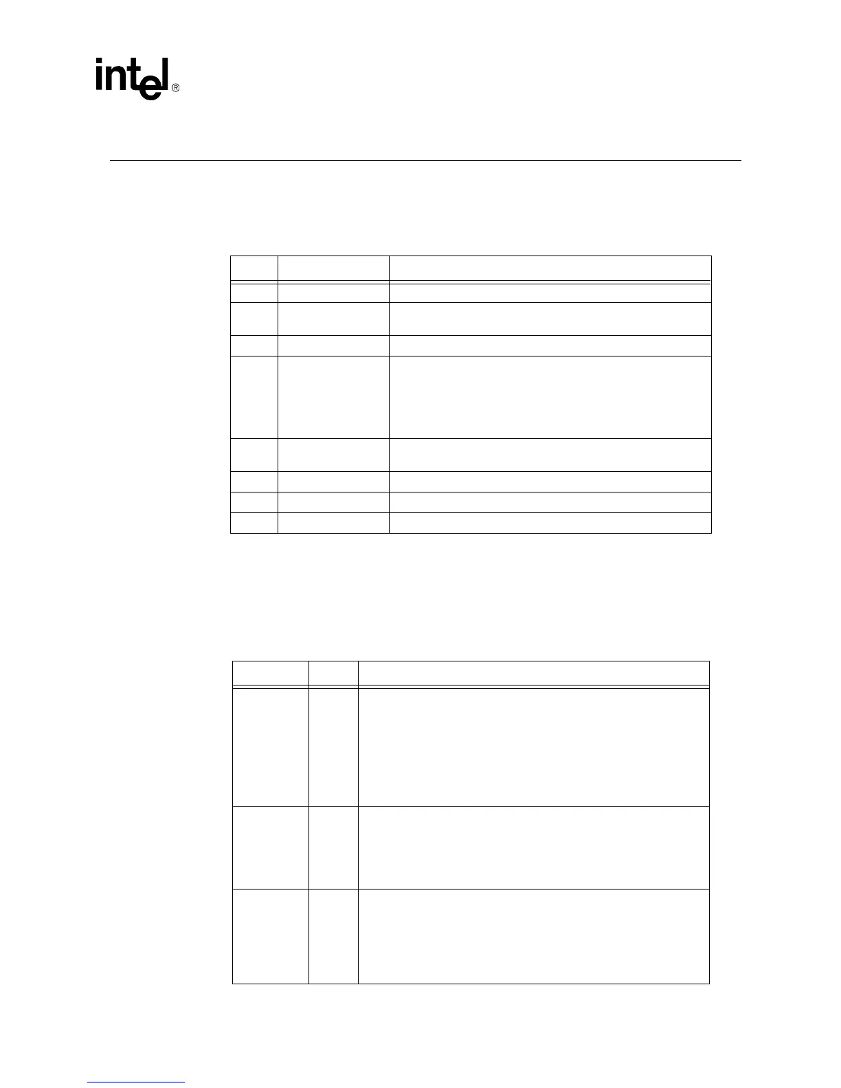
Type Name Description
IN Input The input pin is a standard input onl
si
nal.
OUT Output
The output pin is a Totem Pole Output pin and is a standard
active driver.
T/S Tri-State The tri-state pin is a bidirectional, input/output pin.
S/T/S Sustained Tri-State
The sustained tri-state pin is an active low tri-state si
nal owned
and driven b
one a
ent at a time. The a
ent assertin
the S/T/
S pin low must drive it hi
h at least one clock c
cle before
floatin
the pin. A new a
ent can onl
assert an S/T/S si
nal low
one clock c
cle after it has been tri-stated b
the previous
owner.
O/D Open Drain
The open drain pin allows multiple devices to share this si
nal
as a wired-OR.
A/I Analo
Input The analo
input pin is used for analo
input si
nals.
A/O Analo
Output The analo
output pin is used for analo
output si
nals.
B Bias The bias pin is an input bias.
Symbol Type Name and Function
AD[31:0] T/S
Address and Data.
The address and data lines are multiplexed on
the same PCI pins. A bus transaction consists of an address phase
followed b
one or more data phases. Durin
the address phase, the
address and data lines contain the 32-bit ph
sical address. For I/O,
this is a b
te address; for confi
uration and memor
, it is a Dword
address. The 82559ER uses little-endian b
te orderin
in other
words, AD[31:24] contain the most si
nificant b
te and AD[7:0]
contain the least si
nificant b
te
. Durin
the data phases, the address
and data lines contain data.
C/BE[3:0]# T/S
Command and Byte Enable.
The bus command and b
te enable
si
nals are multiplexed on the same PCI pins. Durin
the address
phase, the C/BE# lines define the bus command. Durin
the data
phase, the C/BE# lines are used as B
te Enables. The B
te Enables
are valid for the entire data phase and determine which b
te lanes
carr
meanin
ful data.
PAR T/S
Parity.
Parit
is even across AD[31:0] and C/BE[3:0]# lines. It is stable
and valid one clock after the address phase. For data phases, PAR is
stable and valid one clock after either IRDY# is asserted on a write
transaction or TRDY# is asserted on a read transaction.Once PAR is
valid, it remains valid until one clock after the completion of the current
data phase. The master drives PAR for address and write data
phases; and the tar
et, for read data phases.
 Loading...


