GD82559ER — Networkin
Silicon
10
Datasheet
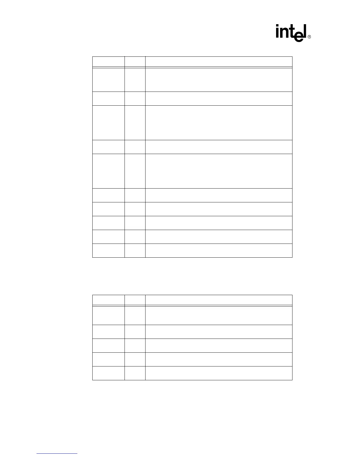
3.4 Testabilit
Port Si
nals
FLA[13]/
EEDI
OUT
Flash Address[13]/EEPROM Data Input.
Durin
Flash accesses,
this multiplexed pin acts as the Flash Address [13] output si
nal.
Durin
EEPROM accesses, it acts as serial output data to the
EEPROM Data Input si
nal.
FLA[12:8] OUT
Flash Address[12:8].
These pins are used as Flash address outputs
to support 128 Kb
te Flash addressin
.
FLA[7]/
CLKENB
T/S
Flash Address[7]/Clock Enable.
This is a multiplexed pin and acts
as the Flash Address[7] output si
nal durin
nominal operation. When
the PCI RST# si
nal is active, this pin acts as input control over the
FLA[16]/CLK25 output si
nal. If the FLA[7]/CLKEN pin is connected to
a pull-up resistor
3.3 K
Ω
, a 25 MHz clock si
nal is provided on the
FLA[16]/CLK25 output; otherwise, it is used as FLA[16] output.
FLA[6:2] OUT
Flash Address[6:2].
These pins are used as Flash address outputs
to support 128 Kb
te Flash addressin
.
FLA[1]/
AUXPWR
T/S
Flash Address[1]/Auxiliary Power.
This multiplexed pin acts as the
Flash Address[1] output si
nal durin
nominal operation. When RST is
active
low
, it acts as the power suppl
indicator. If the 82559ER is fed
PCI power, this pin should be connected to a pull-down resistor; if the
82559ER is fed b
auxiliar
power, this pin should be connected to a
pull-up resistor.
FLA[0] T/S
Flash Address [0].
This pin acts as the Flash Address[0] output
si
nal durin
nominal operation.
EECS OUT
EEPROM Chip Select.
The EEPROM Chip Select si
nal is used to
assert chip select to the serial EEPROM.
FLCS# OUT
Flash Chip Select.
The Flash Chip Select si
nal is active durin
Flash.
FLOE# OUT
Flash Output Enable.
This pin provides an active low output enable
control
read
to the Flash memor
.
FLWE# OUT
Flash Write Enable.
This pin provides an active low write enable
control to the Flash memor
.
Symbol Type Name and Function
Symbol Type Name and Function
TEST IN
Test.
If this input pin is hi
h, the 82559ER will enable the test port.
Durin
nominal operation this pin should be connected to a pull-down
resistor.
TCK IN
Testability Port Clock.
This pin is used for the Testabilit
Port Clock
si
nal.
TI IN
Testability Port Data Input.
This pin is used for the Testabilit
Port
Data Input si
nal.
TEXEC IN
Testability Port Execute Enable.
This pin is used for the Testabilit
Port Execute Enable si
nal.
TO OUT
Testability Port Data Output.
This pin is used for the Testabilit
Port
Data Output si
nal.
 Loading...


