Datasheet
75
Networking Silicon — GD82559ER
NOTES:
Current is measured on all V
CC
pins (V
CC
= 3.3 V).
1. Transmitter peak current is attained by dividing the measured maximum differential output peak voltage by
the load resistance value.
NOTES:
Current is measured on all V
CC
pins (V
CC
= 3.3 V).
1. Transmitter peak current is attained by dividing the measured maximum differential output peak voltage by
the load resistance value.
V
IDR100
Input Differential
Reject Peak Voltage
±100 mV
V
ICM100
Input Common Mode
Voltage
V
CC
/2 V
V
OD100
Output Differential
Peak Voltage
0.95 1.00 1.05 V
I
CCT100
Line Driver Supply
Peak Current
RBIAS100 = 619 Ω 20 mA 1
Table 19. 100BASE-TX Voltage/Current Characteristics
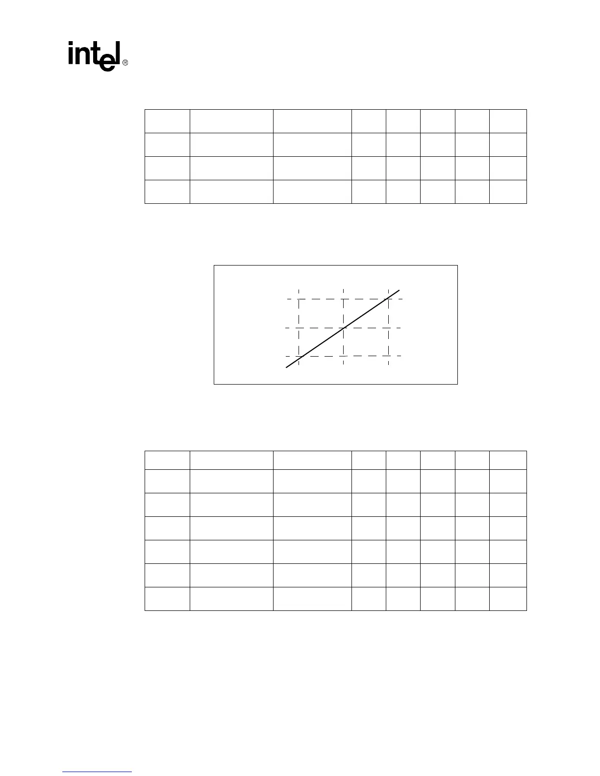
Figure 24. RBIAS100 Resistance Versus Transmitter Current
Rbias100
585 0hm
619 Ohm
650 Ohm
Icct100
19mA
20 mA
21mA
Table 20. 10BASE-T Voltage/Current Characteristics
Symbol Parameter Condition Min Typical Max Units Notes
R
ID10
Input Differential
Impedance
10 MHz 10 KΩ
V
IDA10
Input Differential
Accept Peak Voltage
5 MHz ≤ f ≤ 10 MHz ±585 ±440 ±3100 mV
V
IDR10
Input Differential
Reject Peak Voltage
5 MHz ≤ f ≤ 10 MHz 0 ±440 ±300 mV
V
ICM10
Input Common Mode
Voltage
V
CC
/2 V
V
OD10
Output Differential
Peak Voltage
RL = 100 Ω 2.2 2.8 V
I
CCT10
Line Driver Supply
Peak Current
RBIAS10 = 549 Ω 48 mA 1
 Loading...


