Electrical Specifications
32 Quad-Core Intel® Xeon® Processor 5300 Series Datasheet
Refer to the appropriate platform design guide and the Voltage Regulator Design Guidelines to determine
the total I
TT
drawn by the system. This parameter is based on design characterization and is not tested.
16. I
CC_VTT_OUT
is specified at 1.2 V.
17. I
CC_RESET
is specified while PWRGOOD and RESET# are asserted. Refer to Table 2-26 for the PWRGOOD to
RESET# de-assertion time specification and Table 2-23 for the RESET# Pulse Width specification
.
Notes:
1. Processor or voltage regulator thermal protection circuitry should not trip for load currents greater than
I
CC_TDC
.
2. Not 100% tested. Specified by design characterization.
Notes:
1. Processor or voltage regulator thermal protection circuitry should not trip for load currents greater than
I
CC_TDC
.
2. Not 100% tested. Specified by design characterization.
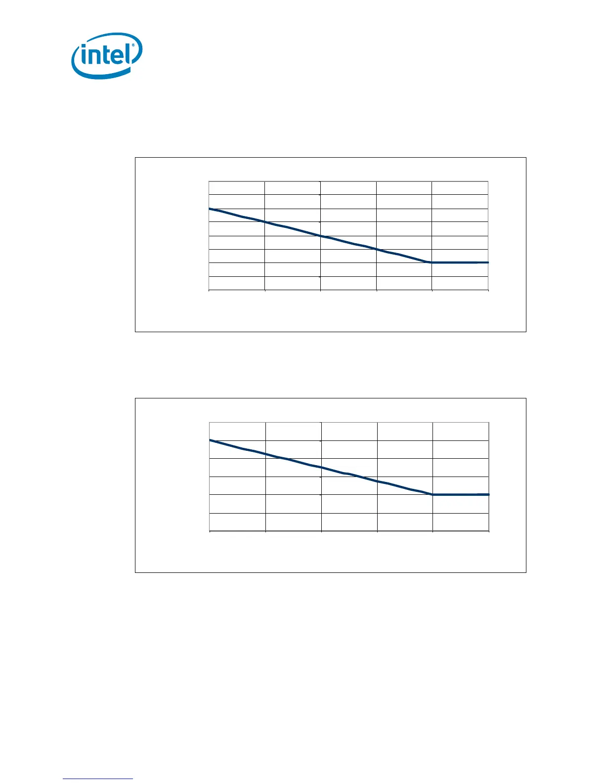
Figure 2-2. Quad-Core Intel® Xeon® Processor E5300 Series Load Current versus Time
60
65
70
75
80
85
90
95
10 0
0.01 0.1 1 10 100 1000
Time Duration (s)
Sustained Current (A)
Figure 2-3. Quad-Core Intel® Xeon® Processor X5300 Series and Load Current versus
Time
10 0
10 5
110
115
12 0
12 5
13 0
0.01 0.1 1 10 100 1000
Time Duration (s)
Sustained Current (A)
 Loading...


