Connector/Header Locations and Pin-outs Intel® Server Board S1200BT TPS
Revision 1.0
Intel order number G13326-003
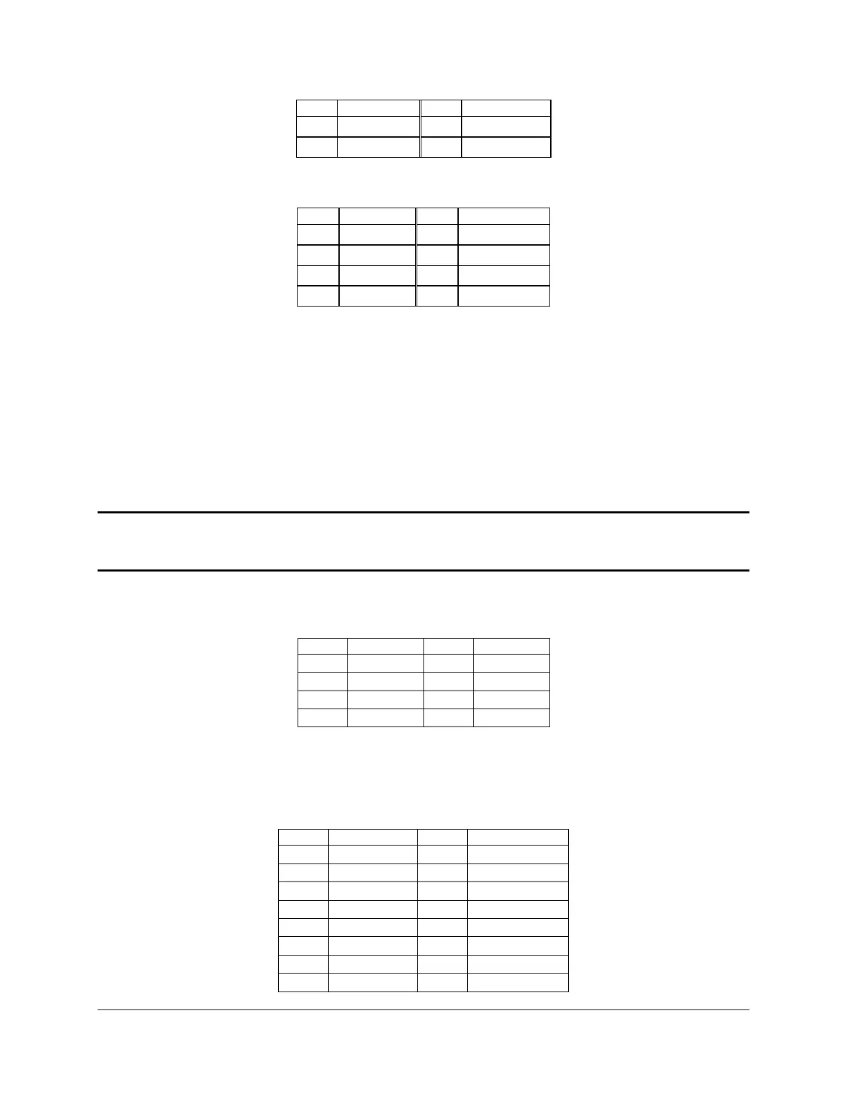
Table 20. SSI Processor 8-PIN Power Connector Pin-out (J9A1)
7.3 System Management Headers
7.3.1 Intel
®
Remote Management Module 4 (Intel
®
RMM4) Lite connetor and
Dedicated NIC connector
An Intel
®
RMM 4 lite connector (J4B1) is included on the server board to support the optional
Intel
®
Remote Management Module 4 lite. This server board does not support third-party
management cards.
Note: This connector is not compatible with the Intel
®
Remote Management Module (Intel
®
RMM), the Intel
®
Remote Management Module 2 (Intel
®
RMM2) or the Intel
®
Remote
Management Module 3 (Intel
®
RMM3)
Table 21. Intel
®
RMM4 lite Connector Pin-out (J4B1)
There is an Intel
®
Remote Management Module 4 (Intel
®
RMM4) Dedicated NIC
connector (J5C1).
Table 22. Dedicated NIC connector for RMM4

 Loading...


