EasyManua.ls Logo

Intel S1200RP User Manual

Intel S1200RP
17 pages
To Next Page IconTo Next Page
To Previous Page IconTo Previous Page
Page #13 background imageLoading...
Page #13 background image
Firmware Upgrade Process
Getting Started Guide 9
2.3 USB Firmware Recovery
The firmware recovery procedure allows the user to recover partially corrupted system
firmware. The firmware is loaded from a FAT32 formatted USB drive by a built-in
recovery routine. We recommend this procedure for recovering systems that fail to
boot after an attempted firmware upgrade or capsule update.
1. Download the development kit firmware images, update tool, and user
documentation from https://firmware.intel.com/develop/server-development-kit
.
2. Power off the target PC and disconnect the power cord.
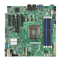
3. Open the case of the target PC and locate the Jumper J2K8 (see Figure 3
). Move
the jumper from “normal mode” (pins 1-2) to “recovery mode” (pins 2-3).
4. Copy the following files to the root folder of a FAT32 formatted USB drive:
FVMAIN.FV
FvUpdate_S1200RP.efi
FvUpdate_S1200RP SDV_RP_B6_release.rom
5. Insert the USB drive into an open USB port on the target PC.
6. Connect the power cord on the target PC and turn the system on. The system
automatically enters recovery mode, which attempts to load firmware from
FVMAIN.FV on the USB drive. This may take several minutes to complete.
7. Once the boot screen appears, enter setup and launch the UEFI Shell.
8. Use the UEFI shell firmware update utility (FvUpdate_S1200RP.efi) to apply the
release firmware image to the motherboard’s SPI memory device:
FvUpdate_S1200RP SDV_RP_B6_release.rom
9. The system will reboot after programming. After reboot, power off the target PC
and disconnect the power cord. Remove the USB drive and return the recovery
jumper to its original position.
10. Power on the target PC. Verify that the firmware functions correctly by entering
setup, verifying the version string matches the expected value for the new
firmware version, and booting to the UEFI shell.
The system shuts down after the update has been applied, then performs one Note:
configuration cycle on the first boot. Wait for this cycle to complete before
entering setup or booting to an operating system.
Upgrading the flash will restore Setup and Boot Manager settings to default Note:
values. Any values previously changed in Setup or Boot Manager will be cleared in
the upgrade process. This includes any boot entries created by a UEFI OS.
2.4 Firmware Installation (Socketed SPI Flash)
This board will not function if the SPI devices are improperly reinstalled. Note:
The complete firmware installation procedure requires the hardware-based SPI flash
programmer. General steps for a complete firmware installation are:
Question and Answer IconNeed help?

Do you have a question about the Intel S1200RP and is the answer not in the manual?

Intel S1200RP Specifications

General IconGeneral
Product TypeServer Board
Form FactorATX
ChipsetIntel C204
Maximum Memory32GB
Power Connectors24-pin ATX, 8-pin EPS
Supported ProcessorIntel Xeon E3-1200 series
Memory Slots4
Supported Memory TypesDDR3
Expansion Slots1 x PCIe 3.0 x16, 1 x PCIe 2.0 x4, 1 x PCIe 2.0 x1, 1 x PCI
Storage Interfaces6x SATA (2x SATA 6Gb/s, 4x SATA 3Gb/s)
Network InterfaceDual Gigabit Ethernet
RAID SupportRAID 0, 1, 5, 10
ManagementIPMI 2.0
Socket TypeSocket H2 (LGA 1155)
USB Ports4 x USB 2.0 (rear), 2 x USB 2.0 (internal)

Summary

Legal Information

Before You Begin

The Development Kit

Overview of the development kit for designing, testing, and debugging UEFI drivers and applications on a compliant system.

Requirements

Lists necessary skills, components, and tools for upgrading or installing a UEFI compliant firmware image on the development kit.

Supported and Recommended Hardware Components

Details supported and recommended PC hardware components for the Intel® Server Board S1200RP UEFI Development Kit.

Using a SPI Flash Programmer

Explains the optional use of a third-party SPI flash programmer for reflashing firmware, especially after corruption.

Jumper Settings for Management Controllers

Recommends jumper settings for disabling BMC and ME to reduce system resets during firmware debugging.

Legacy BIOS Support

Explains how to enable or disable the Compatibility Support Module (CSM) for managing legacy BIOS support.

Network Boot Features

Covers PXE boot support for IPv4/IPv6 and UEFI HTTP/HTTPS boot features.

Firmware Upgrade Process

Firmware Upgrade

Details how to upgrade firmware using the FvUpdate_S1200RP.efi utility from the UEFI Shell.

Capsule Update

Explains the capsule update procedure using the UEFI UpdateCapsule() function with .CAP firmware files.

USB Firmware Recovery

Provides a procedure to recover partially corrupted system firmware using a FAT32 formatted USB drive.

Firmware Installation (Socketed SPI Flash)

Outlines steps for firmware installation on motherboards with socketed SPI flash devices using a hardware programmer.

Firmware Installation (Soldered SPI Flash)

Details firmware installation for motherboards with soldered SPI flash devices using a hardware programmer clip.

User and Reference Documentation

Related product manuals